Ball valve suitable for gas-liquid two-phase flow

A gas-liquid two-phase flow, ball valve technology, applied to valve devices, cocks including cut-off devices, engine components, etc., can solve the problems of complicated installation and disassembly, restrictions on the use of ball valves, and increasing the number of components in the pipeline system, reducing Installation and maintenance costs, increased fluid flow rates, reduced installation effectiveness

Inactive Publication Date: 2016-02-10
天津市精沃阀门科技有限公司
View PDF0 Cites 7 Cited by
  • Summary
  • Abstract
  • Description
  • Claims
  • Application Information

AI Technical Summary

Problems solved by technology

[0002] The opening and closing part of the ball valve is a ball, which is opened and closed by rotating the ball 90° around the axis of the valve stem. The operation is simple and labor-saving, and the valve can be opened or closed with only a small torque. Operation and maintenance and other repair points, but the ball valve is only used for opening and closing and throttling on the straight pipeline, which limits the use of the ball valve. It is usually installed in c

Method used


Image

  • Ball valve suitable for gas-liquid two-phase flow
  • Ball valve suitable for gas-liquid two-phase flow

Examples


Embodiment 1

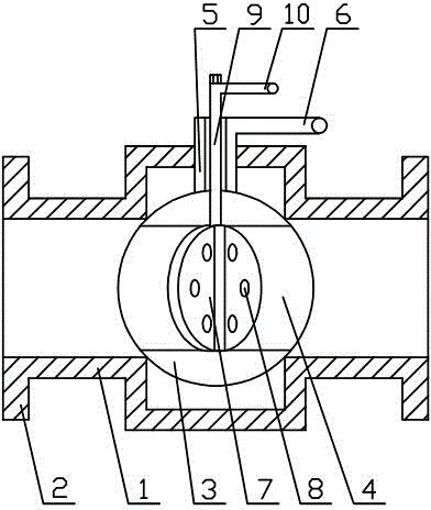
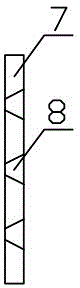
[0014] The present invention includes a valve body 1, a connecting flange 2, a valve core 3, a flow channel 4, a valve stem 5, a switch handle 6, a fluidization inner core 7, a fluidization hole 8, an adjustment rod 9, and a fluidization adjustment handle 10. When installing the connection flange 2 at both ends of the valve body 1, the flow passage 4 is opened on the valve core 3, the fluidization hole 8 is opened on the fluidization inner core 7, and then the fluidization inner core 7 is installed on the circulation passage 4 Then install the valve core 3 inside the valve body 1, and finally install the regulating rod 9 on the inside of the valve stem 5, connect the lower end of the regulating rod 9 with the fluidizing inner core 7, and connect the upper end of the regulating rod 9 with the flow The adjustment handle 10 is connected, the lower end of the valve stem 5 is connected with the valve core 3, and the upper end of the valve stem 5 is connected with the switch handle 6...

Embodiment 2

[0016] When in use, turn the switch handle 6 to connect the flow channel 4 with the pipeline, and adjust the opening of the fluidization inner core 7 by rotating the fluidization adjustment handle 10, so as to achieve the effect of adjusting the fluidization degree, and the gas-liquid two-phase fluid enters the valve The body 1 enters the valve core 3 from the flow passage 4, and then flows out of the valve body 1 after being fluidized by the fluidizing inner core 7.


PUM


Abstract

The invention provides a ball valve suitable for gas-liquid two-phase flow. The ball valve has the flow adjusting function and comprises a valve body, connecting flanges, a valve element, a flow channel, a valve rod, a switch handle, a fluidization inner core, a fluidization hole, an adjusting rod and a fluidization adjusting handle. The two ends of the valve body are provided with the connecting flanges. The valve element is arranged in the valve body. The flow channel is formed in the valve element. The fluidization inner core is arranged inside the flow channel and provided with the fluidization hole. The upper end of the valve element is provided with the valve rod. The upper end of the valve rod is connected with the switch handle. According to the ball valve, the fluidization inner core is additionally arranged, the fluidization adjusting handle can be used for opening adjustment, the fluidization effect is achieved, gas and liquid are evenly mixed, flow can also be adjusted, and the number of auxiliary elements installed in a gas-liquid two-phase flow pipeline is greatly reduced, so that the assembly and disassembly difficulty is lowered, and the installation and maintenance cost is reduced.

Description

technical field [0001] The invention relates to the field of valves, in particular to a ball valve suitable for gas-liquid two-phase flow. Background technique [0002] The opening and closing part of the ball valve is a ball, which is opened and closed by rotating the ball 90° around the axis of the valve stem. The operation is simple and labor-saving, and the valve can be opened or closed with only a small torque. Operation and maintenance and other repair points, but the ball valve is only used for opening and closing and throttling on the straight pipeline, which limits the use of the ball valve. It is usually installed in combination with a flow regulating valve, which increases the difficulty of installation; In phase flow pipelines, gas and liquid usually separate up and down, which brings great troubles to fluid transportation. The existing solution to gas-liquid separation is to install a mixer, which increases the pipeline system. The number of components makes th...

Claims


Application Information

Patent Timeline
IPC IPC(8): F16K5/06F16K5/08
Inventor 李继元
Owner 天津市精沃阀门科技有限公司
Why Eureka
Try Eureka