
Infrared burner of gas cooking appliance

A technology for infrared burners and gas cookers, which is applied in the directions of gas fuel burners, burners, combustion methods, etc., can solve the problems of uneven gas, inconspicuous division of fire power, uneven mixing of gas and air, etc., so as to achieve uniform fire power, The obvious effect of the firepower area inside and outside

Inactive Publication Date: 2016-02-10
梁觐和 +1
View PDF7 Cites 2 Cited by
  • Summary
  • Abstract
  • Description
  • Claims
  • Application Information

AI Technical Summary

Problems solved by technology

The existing problem is: there is a gap between the edge of the flow stabilizer and the inner wall of the burner, and the air tightness is poor, which causes the gas to flow out of the ring-shaped fire ring at the edge of the burner; in addition, the gas and air are not mixed uniformly, and the gas is in The infrared combustion disc is uneven, and the inner and outer firepower divisions on the infrared combustion disc are not obvious

Method used


Image

  • Infrared burner of gas cooking appliance
  • Infrared burner of gas cooking appliance
  • Infrared burner of gas cooking appliance

Examples


Embodiment Construction

[0025] The present invention will be further described below in conjunction with the accompanying drawings.

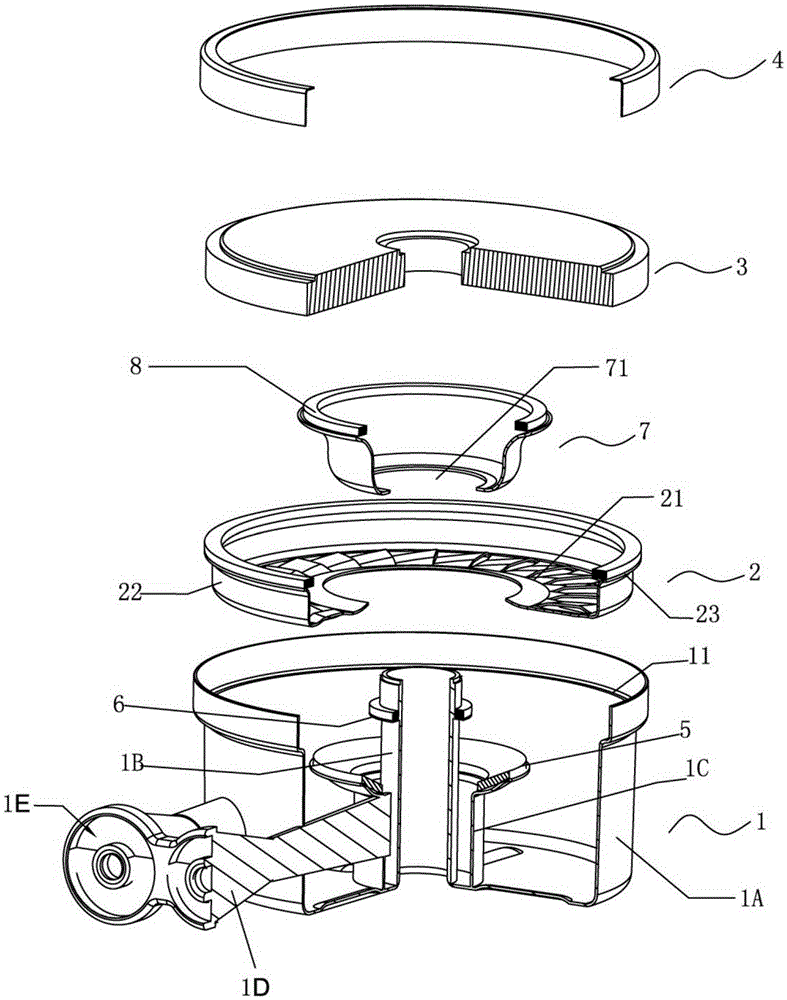
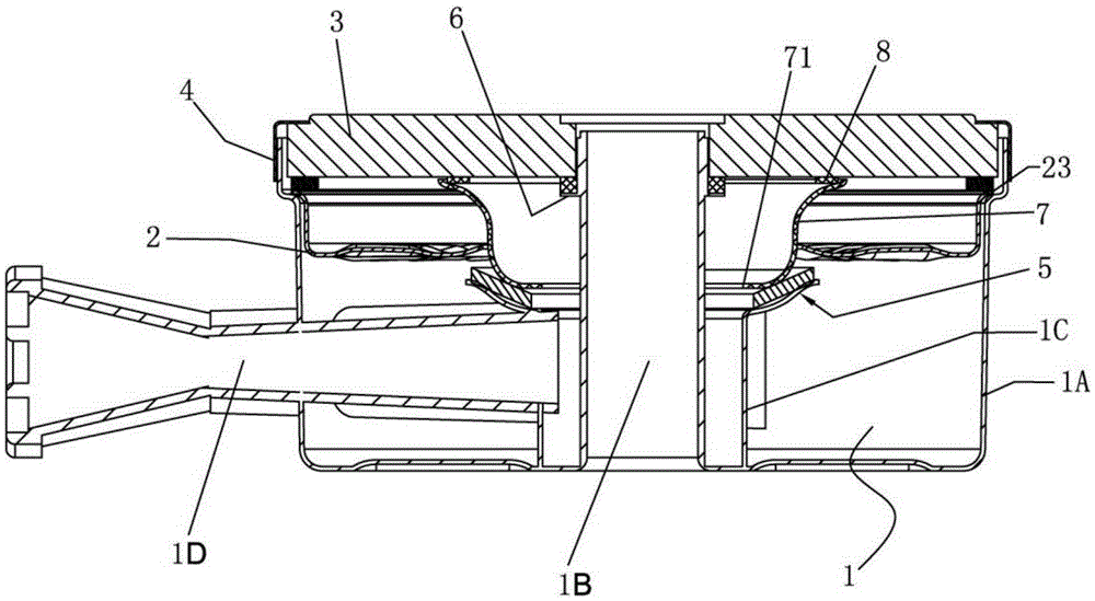
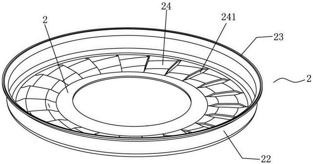
[0026] Such as figure 1 , figure 2 As shown, an infrared burner for a gas cooker includes a burner head 1, a flow stabilizer 2, an infrared burning disc 3 and a fixed ring 4. The burner head 1 includes a cup body 1A with an upper opening, a central pipe 1B, The inner ring wall plate 1C surrounding the central tube, the inner injection tube 1D and the outer injection tube 1E, the inner ring wall plate 1C and the central tube 1B form the inner ring premixing chamber, and the cup body 1A and the inner ring wall plate 1C form the outer ring The premixing chamber, the inner injection tube 1D communicates with the inner ring premixing cavity, the outer injection tube 1E communicates with the outer ring premixing cavity; the upper end of the central tube 1B is inserted into the central hole of the infrared combustion disc 3, and the upper part of the inner wall of the cup b...


PUM


Abstract

The invention discloses an infrared burner of a gas cooking appliance. The infrared burner comprises a furnace head, a flow stabilizing element, an infrared combustion plate and a fixing ring. A supporting plate is arranged on the upper portion of a center pipe of the furnace head. The flow stabilizing element comprises an annular flow stabilizing plate, a barrel-shaped wall plate and an outer folding edge. The annular flow stabilizing plate is provided with a flow stabilizing hole. The burner further comprises a diffusion cup with an upper opening, and a compression hole is formed in a bottom plate of the diffusion cup. The supporting plate and the infrared combustion plate are attached to each other and in gas-tight sealing. The outer folding edge of the flow stabilizing element is arranged on a step of a cup body of the furnace head. The infrared combustion plate is disposed on the outer folding edge of the flow stabilizing element. The diffusion cup is arranged on an annular base plate of the furnace head and is in gas-tight sealing. The upper open end of the diffusion cup and the lower surface of the infrared combustion plate are attached to each other and are in gas-tight sealing. The compression hole of the diffusion cup and the center pipe of the furnace head form an annular compression hole. By the adoption of the structure, air and gas are mixed evenly, and the infrared burner has the advantages that fire distribution of the infrared combustion plate is uniform, and an inner fire area and an outer fire area are obvious.

Description

technical field [0001] The invention relates to a burner for a gas cooker, in particular to an infrared burner. Background technique [0002] In the current prior art, the infrared burner of a gas cooker includes a burner head, a flow stabilizer, an infrared burning disc and a fixed ring. The inner injection tube and the outer injection tube, the inner ring wall plate and the central tube form the inner ring premixing cavity, the cup body and the inner ring wall plate form the outer ring premixing cavity, and the inner injection tube communicates with the inner ring premixing cavity. The outer injection tube communicates with the outer ring premixing chamber; the upper end of the central tube is inserted into the central hole of the infrared burning disc, and the steps in the cup support the infrared burning disc. The existing problem is: there is a gap between the edge of the flow stabilizer and the inner wall of the burner, and the air tightness is poor, which causes the ...

Claims


Application Information

Patent Timeline
Patent Type & Authority Applications(China)
IPC IPC(8): F23D14/02F23D14/12F23D14/46
Inventor 梁觐和梁赞棠
Owner 梁觐和
Learn More