Antenna near-field measurement method based on unmanned plane

A measurement method and unmanned aerial vehicle technology, applied in the field of radio holography, can solve problems such as the inability to measure antenna near-field data, and achieve the effects of multiple corrections, wide adaptability, and high cost performance

Active Publication Date: 2016-02-10
SHANGHAI JIAO TONG UNIV
View PDF11 Cites 24 Cited by
  • Summary
  • Abstract
  • Description
  • Claims
  • Application Information

AI Technical Summary

Problems solved by technology

However, because this method is limited by the fixed position of the beacon, it cannot measure the near-field data of the antenna at various elevations, especially for large radio telescopes, the deformation of the main refle

Method used


Image

  • Antenna near-field measurement method based on unmanned plane

Examples


Embodiment Construction

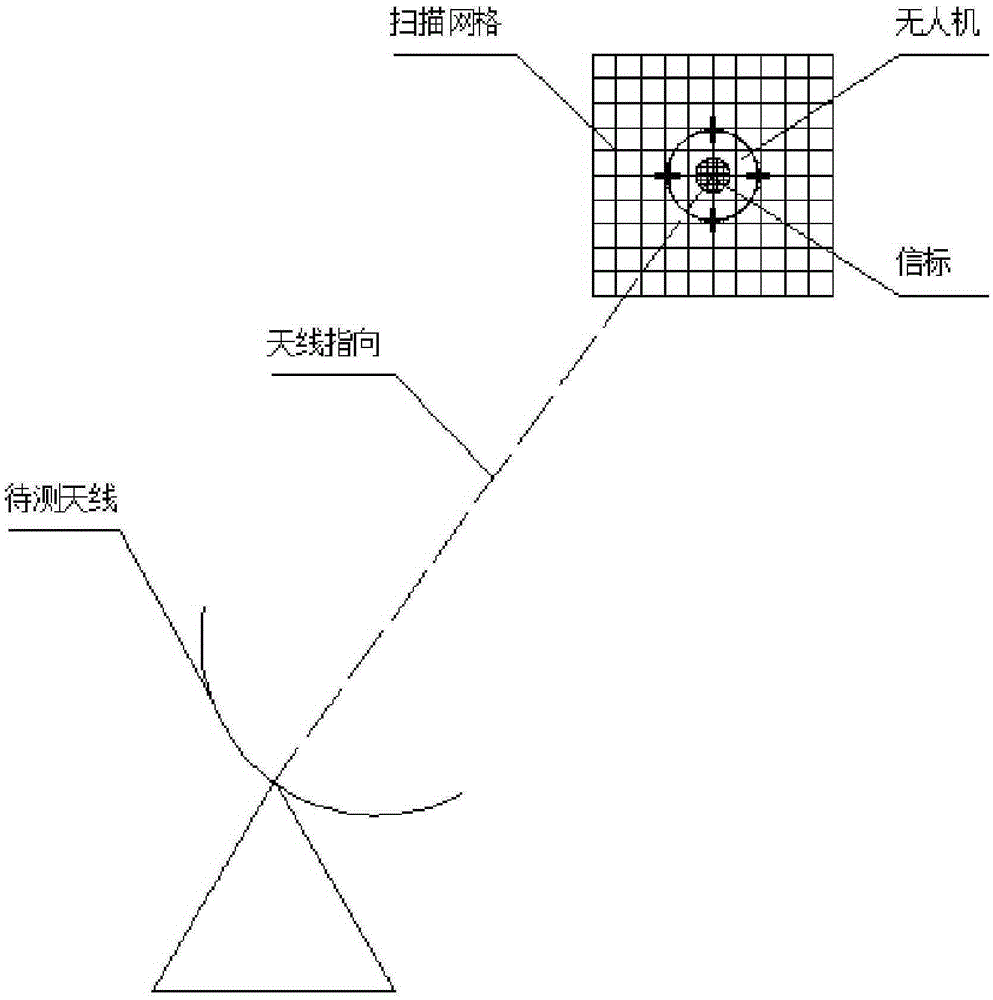
[0017] Such as figure 1 As shown, this embodiment includes the following steps:

[0018] Step 1: The antenna to be tested is fixed under the detection azimuth and pitch attitude, and the UAV is used to carry the beacon and positioning equipment to control the UAV to fly around the antenna to be tested in the near field area of ​​the antenna. The signal obtained by the antenna to be tested is The marking data determines the moment when the drone is pointed to by the antenna, and the spatial coordinates of the drone at the corresponding moment are determined by the laser rangefinder trajectory tracking device, and the spatial coordinates are used as the scanning center of the drone.

[0019] The antenna to be tested adopts but is not limited to a parabolic antenna.

[0020] Said beacons use but are not limited to wireless signal transmitters.

[0021] The flight mentioned specifically means that the distance between the UAV and the antenna to be tested is within the near-field...


PUM


Abstract

Provided is an antenna near-field measurement method based on an unmanned plane, which collects the space coordinate information of an unmanned plane with a beacon, and signal information from the beacon received by an antenna to be measured, thereby establishing the relation between the receiving pose of the antenna to be measured and a signal source space position, and realizing near-field measurement. The antenna near-field measurement method is specific to near-field measurement, has the advantages of simple operation, high cost performance, wide adaptability and high test precision, and is especially suitable for large-scale antenna measurement.

Description

technical field [0001] The invention relates to a technology in the field of radio holography, in particular to an antenna near-field measurement method based on an unmanned aerial vehicle. Background technique [0002] Antenna near-field measurement is an important part of radio holography. On the one hand, through the near-field measurement, the near-far field transformation can be used to obtain the far-field observation performance of the antenna. On the other hand, the diagnosis of the deformation of the antenna aperture surface can be realized through the transformation between the near-field aperture fields. [0003] At present, the common method of antenna near-field measurement is to place a beacon at a certain distance from the antenna to be tested, and scan the beacon by adjusting the pitch and azimuth of the antenna to be tested, so as to realize the near-field measurement of the antenna. However, because this method is limited by the fixed position of the beac...

Claims


Application Information

Patent Timeline
IPC IPC(8): G01R29/10
Inventor 叶骞刘抗抗徐月暑
Owner SHANGHAI JIAO TONG UNIV
Why Eureka
Try Eureka