Multi-plane-mirror reflection tracking pan-tilt system calibration method

A calibration method and plane mirror technology, applied in image data processing, instrumentation, calculation, etc.

Active Publication Date: 2016-02-10
ZHEJIANG UNIV
View PDF4 Cites 4 Cited by
  • Summary
  • Abstract
  • Description
  • Claims
  • Application Information

AI Technical Summary

Problems solved by technology

Therefore, if only the traditional calibration method is used for calibration, it can only solve the calibration problem between the virtual camera

Method used


Image

  • Multi-plane-mirror reflection tracking pan-tilt system calibration method
  • Multi-plane-mirror reflection tracking pan-tilt system calibration method
  • Multi-plane-mirror reflection tracking pan-tilt system calibration method

Examples


Embodiment Construction

[0026] The technical solution of the present invention will be further described through specific implementation examples below in conjunction with the accompanying drawings.

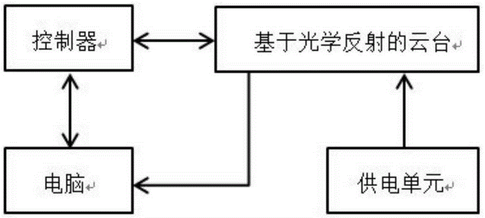
[0027] figure 1 It is a structural schematic diagram of the system of the present invention. The system is a pan-tilt visual tracking system based on optical reflection. The system includes a pan-tilt based on optical reflection, a controller, a computer, and a power supply unit. The controller is connected to receive instructions from the controller and feed back the state of the rotary drive unit. The controller is connected to the computer to receive instructions and feedback status. The pan / tilt based on optical reflection is also connected to the computer to transmit the images collected by the camera to the computer. The optically reflective pan / tilt is connected to a power supply unit.

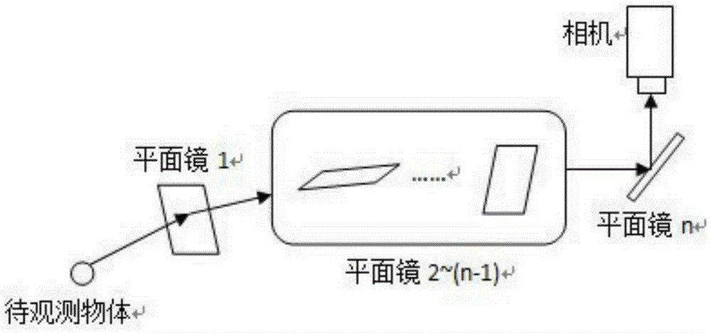
[0028] figure 2 It is a schematic diagram of a pan / tilt based on optical reflection (n≥2) using n plane mir...


PUM


Abstract

The present invention discloses a multi-plane-mirror reflection tracking pan-tilt system calibration method. The method comprises: calibrating a pan-tilt system initially by using a Zhang Zhengyou calibration method or other conventional calibration methods to acquire an intrinsic and extrinsic parameter matrix of a virtual camera formed by n times of mirror imaging of an actual camera, wherein the intrinsic parameter of the virtual camera is an intrinsic parameter of the actual camera because an internal structure of the virtual camera is the same as an internal structure of the actual camera. The method solves the calibration problem of using reflections of n mirrors to track optical reflection pan-tilt of an object, so that the pan-tilt can be brought into contact with to-be-viewed space and accepts a coordinate instruction of a to-be-viewed object given by the exterior, locates a location of the to-be-viewed object quickly and accurately, and thus even if the object disappears from vision, the object can be followed up quickly; and the method is performed in combination with the conventional calibration method, the required calibration device is the same as that of the conventional calibration method, and the method is simple and convenient.

Description

technical field [0001] The invention belongs to the field of machine vision, in particular to a calibration method for a multi-plane mirror reflection tracking pan-tilt system. Background technique [0002] In the image measurement process and machine vision applications, in order to determine the relationship between the position of a certain point on the surface of a space object and its corresponding point in the image, it is necessary to establish a geometric model of camera imaging, and these geometric model parameters are camera parameters. Under most conditions, these parameters must be obtained through experiments and calculations. This process of solving parameters is called camera calibration. The traditional methods of camera calibration include Zhang Zhengyou calibration method, Tsai algorithm and so on. Taking the classic Zhang Zhengyou calibration method as an example, this method only needs the camera to directly observe the image of a checkerboard plate at t...

Claims


Application Information

Patent Timeline
IPC IPC(8): G06T7/00
Inventor 章逸丰吴珺熊蓉
Owner ZHEJIANG UNIV
Why Eureka
Try Eureka