Pilot transmission method, channel measurement method and device in mimo system

A channel measurement and pilot measurement technology, which is applied in transmission systems, digital transmission systems, diversity/multi-antenna systems, etc., can solve problems such as inflexible pilot resource allocation

Active Publication Date: 2019-04-02
DATANG MOBILE COMM EQUIP CO LTD
View PDF7 Cites 0 Cited by
  • Summary
  • Abstract
  • Description
  • Claims
  • Application Information

AI Technical Summary

Problems solved by technology

[0013] The purpose of the present invention is to provide a pilot transmission method, channel measurement method and device in a MIMO system to solve the problem of inflexible pilot resource allocation

Method used


Image

  • Pilot transmission method, channel measurement method and device in mimo system
  • Pilot transmission method, channel measurement method and device in mimo system
  • Pilot transmission method, channel measurement method and device in mimo system

Examples


Embodiment Construction

[0120] The technical solution provided by the embodiments of the present invention is applied to a MIMO system, and the MIMO system may be, but not limited to, a 3D / FD MIMO system, or other MIMO systems.

[0121] The technical solutions provided by the embodiments of the present invention will be described in detail below in conjunction with the accompanying drawings.

[0122] The implementation of the method provided by the embodiment of the present invention on the network side is as follows image 3 As shown, it specifically includes the following operations:

[0123] Step 300, using different beamforming matrices to perform beamforming on different subframes where the same pilot resource is located.

[0124] Wherein, the pilot resources are composed of a group of time-frequency resources, and these time-frequency resources are distributed in different subframes. Therefore, the subframe where the pilot resource is located refers to the subframe where a group of time-frequ...


PUM


Abstract

Disclosed are a pilot frequency sending method and a channel measurement method and apparatus. The pilot frequency sending method comprises: sending a pilot frequency signal in various subframes where the same pilot frequency resource is located; and indicating a subframe, capable of being used for performing channel measurement, in the subframes where the pilot frequency resource is located for a user equipment. In the technical solution provided by the present application, configured pilot frequency resources can be fewer than the quantity of beam forming matrices, thereby reducing the overhead of the pilot frequency resource, and reducing the pilot frequency feedback overhead. In the technical solution provided by the present application, a network side controls a user equipment to perform channel measurement on which subframes, thereby improving the CSI reporting precision.

Description

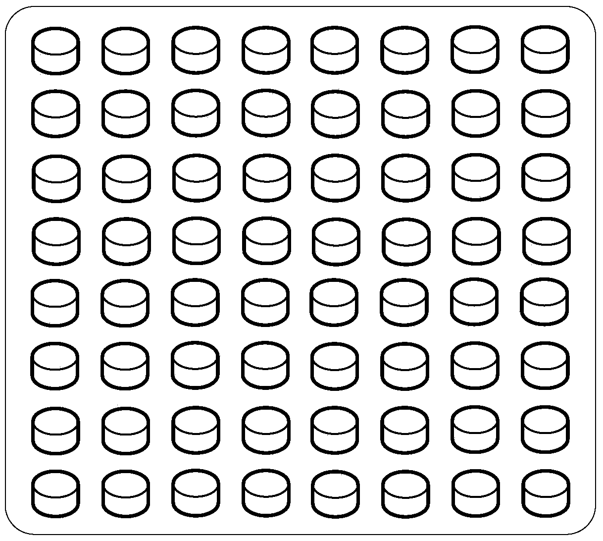
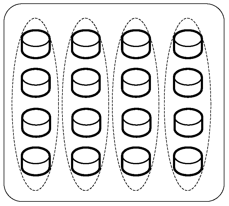
[0001] This application claims the priority of the Chinese patent application submitted to the China Patent Office on July 30, 2014, with the application number 201410371543.4, and the title of the invention is "a pilot transmission method, measurement method and device in a MIMO system", all of which The contents are incorporated by reference in this application. technical field [0002] The present invention relates to the technical field of wireless communication, in particular to a pilot transmission method, a channel measurement method and a device in a MIMO system. Background technique [0003] The two-dimensional antenna structure in a 3-dimensional (3D) multiple-input multiple-output (Multiple-Input Multiple-Output, MIMO) system is as follows figure 1 shown. figure 1 Shown is a single-polarized antenna structure with 64 antennas, where each cylindrical figure represents an antenna. It should be pointed out that in the 3D MIMO system, the number of antennas in the t...

Claims


Application Information

Patent Timeline
Patent Type & Authority Patents(China)
IPC IPC(8): H04B7/06H04L5/00
CPCH04B7/06H04L5/00
Inventor 陈润华高秋彬
Owner DATANG MOBILE COMM EQUIP CO LTD
Why Eureka
Try Eureka