Method for performing joint jitter and amplitude noise analysis on a real time oscilloscope

A noise, amplitude technique for performing joint jitter and amplitude noise analysis on real-time oscilloscopes

Active Publication Date: 2016-02-10
TEKTRONIX INC
View PDF7 Cites 5 Cited by
  • Summary
  • Abstract
  • Description
  • Claims
  • Application Information

AI Technical Summary

Problems solved by technology

Furthermore, real-time oscilloscopes process valuable information about the dynamics of the waveform in the neighborhood of the target analysis point, such as the slope of the leading edge, but the method of US Patent No. 7,522,661 fails to exploit this information

Method used


Image

  • Method for performing joint jitter and amplitude noise analysis on a real time oscilloscope
  • Method for performing joint jitter and amplitude noise analysis on a real time oscilloscope
  • Method for performing joint jitter and amplitude noise analysis on a real time oscilloscope

Examples


Embodiment Construction

[0016] In the drawings, which are not necessarily to scale, like or corresponding elements of the disclosed systems and methods are labeled with like reference numerals.

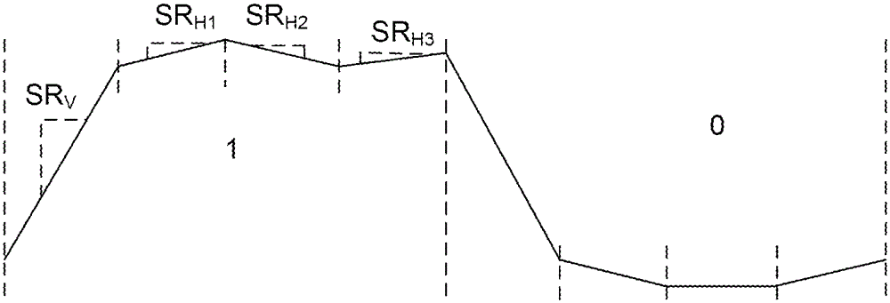
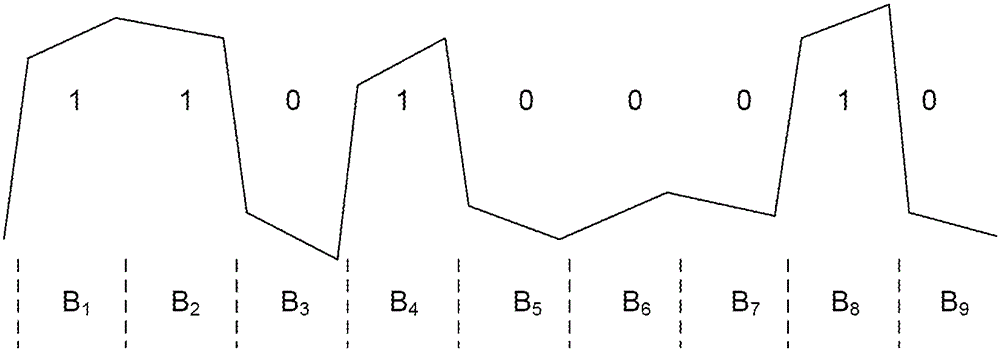
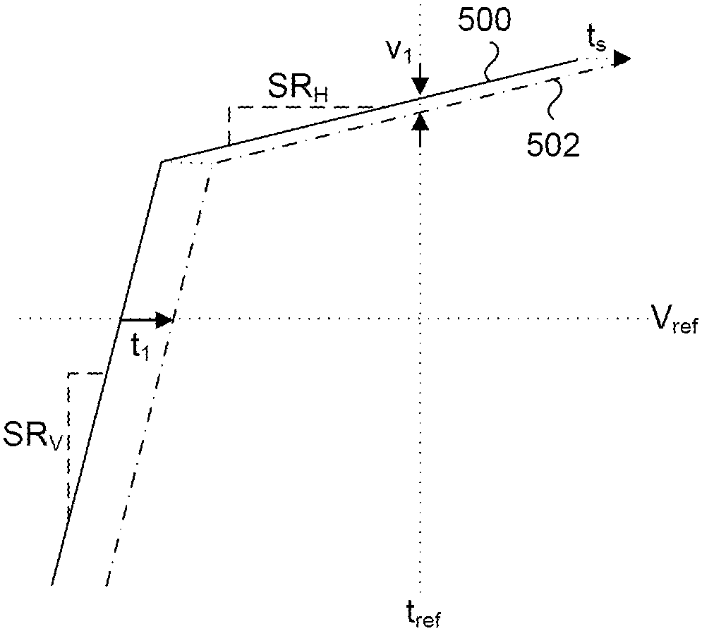
[0017] The disclosed technique uses information from the vertical displacement at the center of each bit and the horizontal displacement on each edge to give very high processing efficiency that matches well with the characteristics of real-time oscilloscopes. That is, the method of the disclosed technology uses all unit intervals in the pattern and does not rely solely on measurement locations with zero slew rate.

[0018] now refer to figure 1 , shows a representative block diagram of a real-time oscilloscope for implementing a method of performing joint jitter and noise analysis according to an embodiment of the present invention. Although a real-time oscilloscope is shown and discussed below, any type of test and measurement instrument capable of obtaining a suitable representation of a time-domain wave...


PUM


Abstract

A method for determining jitter and noise of an input signal. The method includes acquiring one or more uncorrelated waveform records by an acquisition unit of a test and measurement instrument, determining a correlated waveform from the acquired waveform(s), dividing the correlated waveform into unit intervals, dividing an uncorrelated waveform into unit intervals, measuring a timing displacement (t 1 ) between the correlated waveform and the uncorrelated waveform for each unit interval to form an apparent-jitter array ([t 1 ]), measuring a voltage displacement (V 1 ) between the correlated waveform and the uncorrelated waveform for reach unit interval to form an apparent-noise array ([V 1 ]), calculating a horizontal shift (t s ) between the correlated waveform and the uncorrelated waveform for each unit interval to form a compensated edge time array ([t s ]), and calculating a vertical shift (V s ) between the correlated waveform and the uncorrelated waveform for each unit interval to form a compensated amplitude voltage array ([V s ]).

Description

[0001] priority [0002] This application claims the benefit of US Provisional Application No. 62 / 031,069, filed July 30, 2014, which is hereby incorporated by reference in its entirety. technical field [0003] The present disclosure relates to performing joint jitter and amplitude noise analysis to generate two-dimensional probability density functions and bit error rate eye diagrams. Background technique [0004] The analysis of timing jitter has been of interest in the field of high speed serial data communications. Many concepts are formalized with the publication of the Fiber Channel methodology for jitter and signal quality specifications (Technical Report TR-35-2004, Washington DC: ANSI / INCITS, 2004). The method described in Fiber Channel Methodology for Jitter and Signal Quality Specifications allows timing jitter analysis at a specific reference voltage. The reference voltage corresponds to a horizontal slice through the eye diagram at a given level. However, th...

Claims


Application Information

Patent Timeline
Patent Type & Authority Applications(China)
IPC IPC(8): H04B17/00
CPCG01R13/0272G01R13/029G01R29/26G01R31/31709G01R31/3171G01R31/31711H04L1/205
Inventor M.L.京瑟K.谭
Owner TEKTRONIX INC
Why Eureka
Try Eureka