Electronic component mounting system and electronic component mounting method
An electronic component installation and electronic component technology, applied in the direction of electrical components, electrical components, etc., can solve problems such as unqualified substrates, product quality decline, and identifier reading operations are not properly performed, and achieve suppression of unqualified substrates, suppression The effect produced
- Summary
- Abstract
- Description
- Claims
- Application Information
AI Technical Summary
Problems solved by technology
Method used
Image

Examples
no. 1 Embodiment approach >
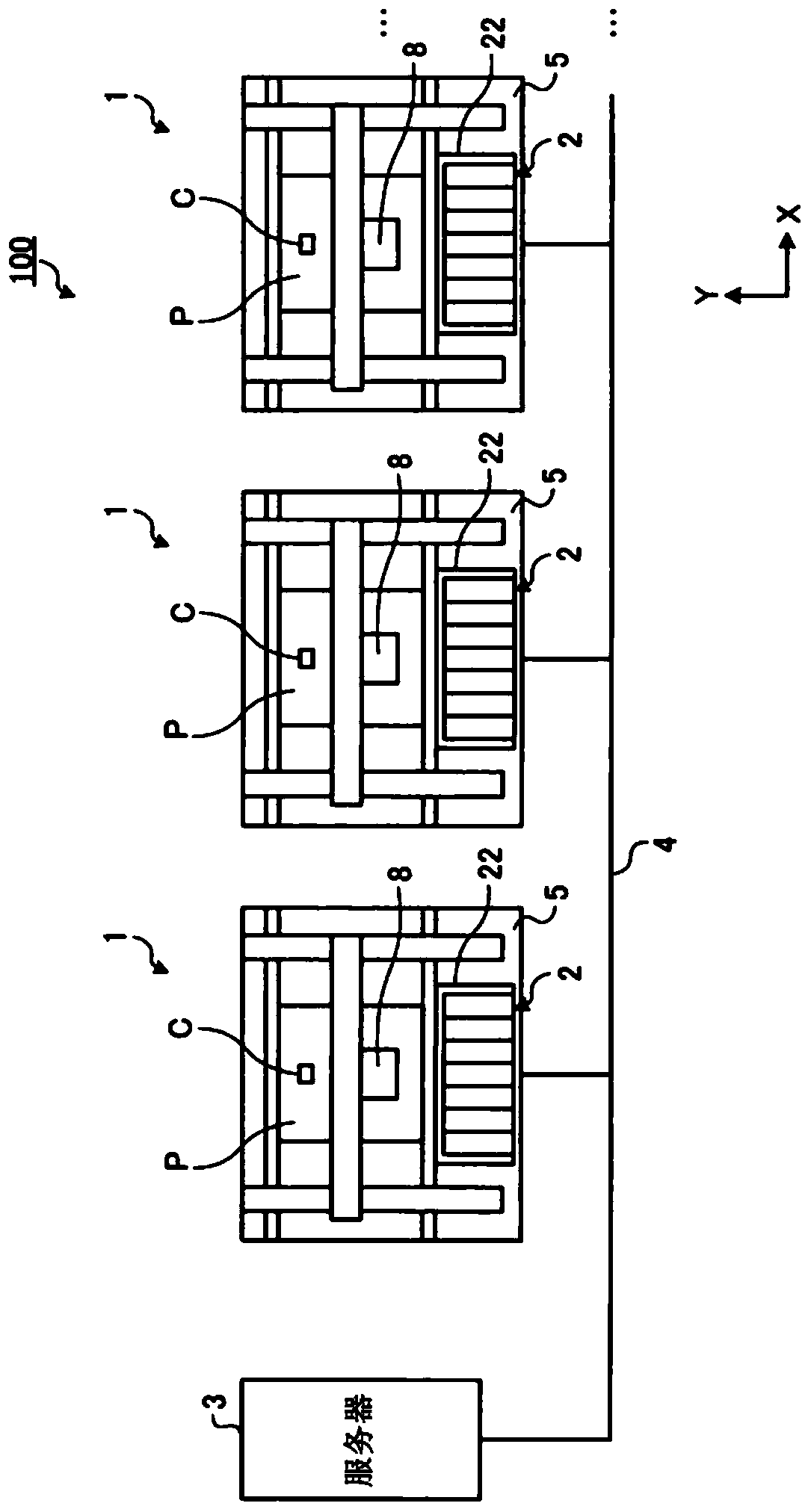
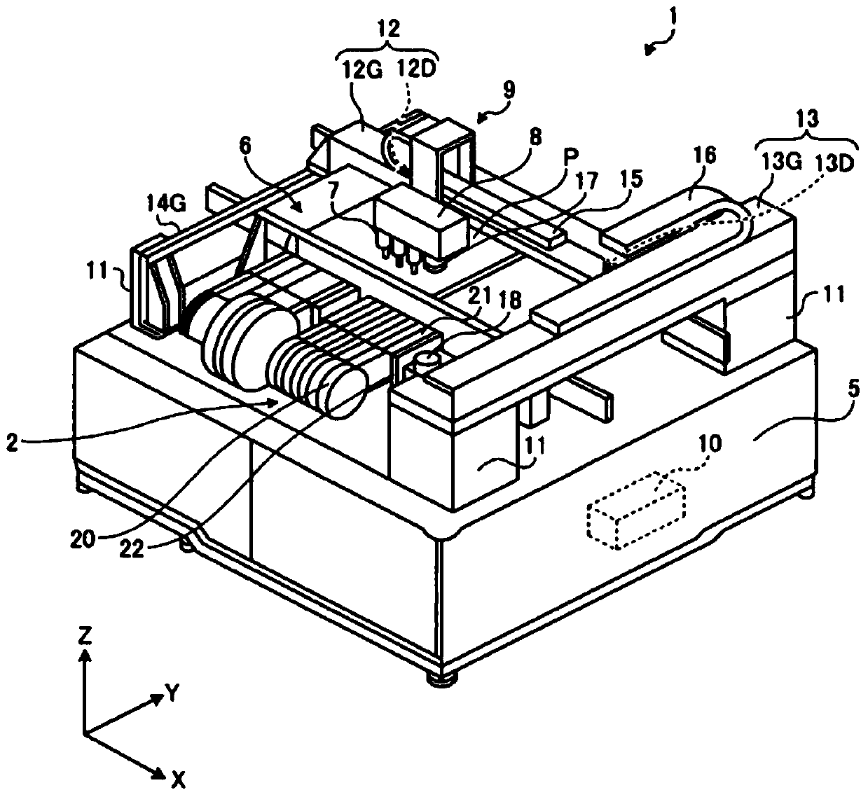
[0094] The first embodiment will be described. figure 1 It is a schematic diagram which shows an example of the electronic component mounting system 100 which concerns on this embodiment. figure 2 It is a perspective view which shows an example of the mounting apparatus 1 which concerns on this embodiment.
[0095] Such as figure 1 As shown, the electronic component mounting system 100 has the mounting apparatus 1 which mounts the electronic component C on the board|substrate P, and the server 3 which manages the mounting apparatus 1. As shown in FIG. The mounting apparatus 1 has the supply apparatus 2 which can supply the electronic component C, and mounts the electronic component C of the supply apparatus 2 on the board|substrate P. As shown in FIG.
[0096] In this embodiment, the electronic component mounting system 100 has a plurality of mounting apparatuses 1 . The supply device 2 is provided on each of the plurality of mounting devices 1 . The server 3 and each of ...
no. 2 Embodiment approach >
[0243] A second embodiment will be described. In the following description, the same reference numerals are assigned to the same or equivalent components as those of the above-mentioned embodiment, and the description thereof is simplified or omitted.
[0244] In the above-mentioned first embodiment, when it is determined that the remaining number of electronic components C of the feeder 21 is zero, the operation device 51 is invalidated. In this embodiment, an example will be described in which the operating device 51 is disabled when it is determined that the remaining number of electronic components C in the feeder 21 is less than or equal to the first threshold and the number of retries is greater than or equal to the second threshold. When it is determined that the remaining number of electronic components C in the feeder 21 is greater than the first threshold value, the operation device 51 is not invalidated.
[0245] In the present embodiment, when the invalidation uni...
no. 3 Embodiment approach
[0278] A third embodiment will be described. In the following description, the same reference numerals are assigned to the same or equivalent components as those of the above-mentioned embodiment, and the description thereof is simplified or omitted.
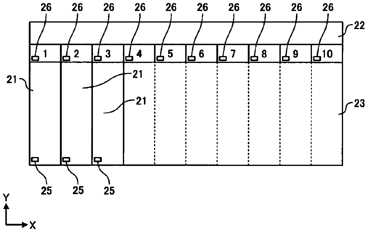
[0279] In this embodiment, an example in which the feeder 21 is an electric feeder will be described. Figure 10 It is a schematic diagram which shows an example of the electric power supplier 210. FIG. Electric power supplier 210 is supplied with electric power from power supply device 220 . The electric feeder 210 has a motor, and supplies the holding belt with power generated by the motor.
PUM
 Abstract
Description
Claims
Application Information