Supercharge Your Innovation With Domain-Expert AI Agents!

Automatic discharging device of upper discharging centrifugal machine

An automatic discharge device and centrifuge technology, applied in the field of centrifuges, can solve the problems of lack of automation and manual operation of electric hoists, and achieve the effects of saving space and cost, simple structure, and easy operation

Inactive Publication Date: 2016-02-17
苏州盛天力离心机制造有限公司
View PDF13 Cites 0 Cited by
  • Summary
  • Abstract
  • Description
  • Claims
  • Application Information

AI Technical Summary

Problems solved by technology

However, the hanging bag centrifuge has the following disadvantages: 1. It is necessary to set up the track of the electric hoist on the upper part of the centrifuge, so a certain height and space must be guaranteed
2. The electric hoist needs manual operation
3. For closed centrifuges, the shell cover must be opened every time unloading

Method used


Image

  • Automatic discharging device of upper discharging centrifugal machine
  • Automatic discharging device of upper discharging centrifugal machine
  • Automatic discharging device of upper discharging centrifugal machine

Examples


Embodiment Construction

[0016] The automatic discharge device of an upper discharge centrifuge according to the present invention will be further described in detail through specific embodiments below.

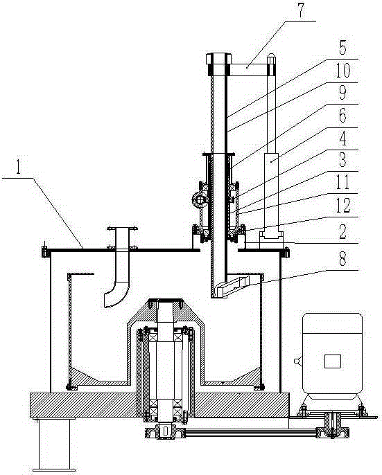
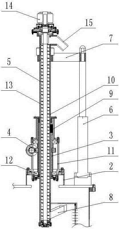
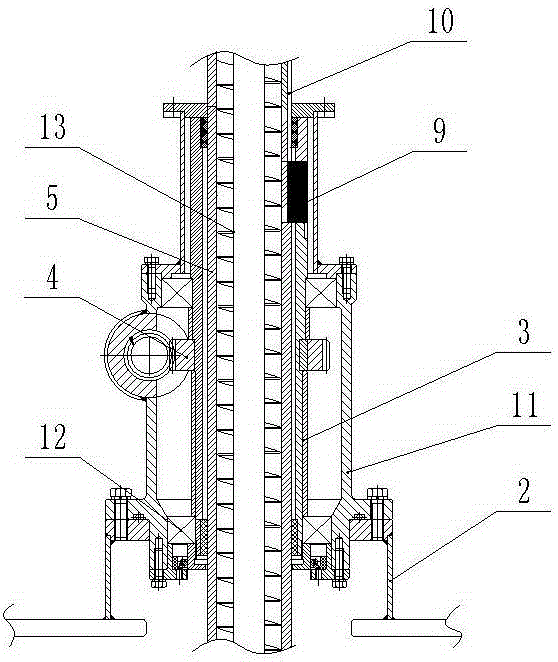
[0017] like figure 1 , image 3 As shown, the automatic discharge device of the upper discharge centrifuge includes a bracket 2 arranged on the centrifuge casing cover 1, and the bracket 2 is provided with a rotatable rotating sleeve 3 and a rotating shaft that drives the rotating sleeve 3 to rotate. Driving device. In this embodiment, the rotating driving device includes a rotating gear 4 arranged outside the rotating sleeve 3, and the rotating gear 4 is connected with a rotating oil cylinder (not shown in the figure) through a rack. The structure of the rotary driving device can also adopt other traditional driving methods, which all belong to the protection category of the present invention. The rotating sleeve 3 is provided with a lifting tube 5 that can move in the axial direction, and the lif...


PUM


Abstract

The invention relates to an automatic discharging device of an upper discharging centrifugal machine. The automatic discharging device comprises a support arranged on a shell cover of the centrifugal machine. A rotatable rotary casing pipe and a rotating drive device for driving the rotary casing pipe to rotate are arranged in the support. A lifting pipe capable of moving in the axial direction is arranged in the rotary casing pipe. The lifting pipe and the rotary casing pipe are locked in the annular direction. The shell cover of the centrifugal machine is provided with an axial movement drive device used for driving the lifting pipe to axially move. The lifting pipe is of a hollow structure. A hollow inclined pipe communicated with the interior of the lifting pipe is arranged on the lower portion of the lifting pipe. One end of the hollow inclined pipe is connected with the lifting pipe, and the other end of the hollow inclined pipe is arranged in an upward inclining manner. The lower portion of the lifting pipe and the hollow inclined pipe are located in a rotary drum of the centrifugal machine. A discharge device used for discharging filter cakes is arranged on the lifting pipe. A rail for an electric hoist does not need to be erected, and space and cost are saved. In addition, during discharging, the shell cover does not need to be opened, operation is easier and more convenient, and automatic discharging is achieved.

Description

technical field [0001] The invention relates to the technical field of centrifuges, in particular to an automatic discharge device for an upper discharge centrifuge. Background technique [0002] The upper discharge centrifuge is widely used in manufacturing enterprises due to its simple structure, convenient installation and maintenance, and low price. The unloading method of the upper unloading centrifuge was initially manual unloading, so the labor intensity was high and the unloading efficiency was low. In the late 1990s, a hanging bag centrifuge appeared, which used an electric hoist , hang the hanger on the hanger, hang the filter cake and filter bag from the upper part of the centrifuge with the hanger, realize the unloading, improve the efficiency and reduce the labor intensity. But the hanging bag centrifuge has the following disadvantages: 1. The track of the electric hoist needs to be erected on the upper part of the centrifuge, so a certain height and space must...

Claims


Application Information

Patent Timeline
Patent Type & Authority Applications(China)
IPC IPC(8): B04B11/04
Inventor 陈志才
Owner 苏州盛天力离心机制造有限公司
Features
  • R&D
  • Intellectual Property
  • Life Sciences
  • Materials
  • Tech Scout
  • Unparalleled Data Quality
  • Higher Quality Content
  • 60% Fewer Hallucinations
Learn More