
Automatic copper pipe drawing device

A kind of drawing equipment and automatic technology, applied in the field of copper tube automatic drawing equipment, to achieve the effect of automatic drawing and fast and convenient operation

Inactive Publication Date: 2016-02-17
HEFEI GREAT WALL REFRIGERATION TECH
View PDF0 Cites 2 Cited by
  • Summary
  • Abstract
  • Description
  • Claims
  • Application Information

AI Technical Summary

Problems solved by technology

[0003] In order to solve the problems of using the transition tube alone, the invention provides a copper tube automatic drawing equipment
This equipment can form large-diameter refrigeration pipe parts into pipe parts with a small-diameter transition area by drawing, which solves the problem of using transition pipes alone

Method used


Image

  • Automatic copper pipe drawing device

Examples


Embodiment Construction

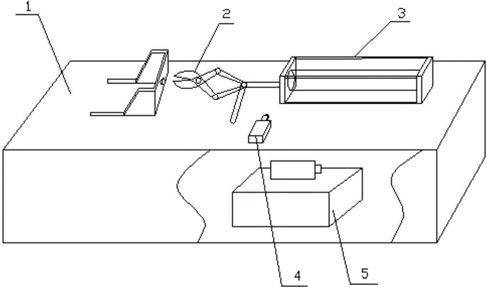
[0012] Referring to the accompanying drawings, the copper pipe automatic drawing equipment includes a fuselage 1, a hydraulic system 5, an automatic clamping pliers 2 and a drawing device, the hydraulic system 5 is installed inside the fuselage 1, and the upper surface of the fuselage 1 is installed There are automatic clamping pliers 2 and a drawing device, and the drawing device includes a drawing hydraulic cylinder 3 and a drawing length detection travel switch 4, and the proportional regulating valve adopted in the hydraulic system 5 is a pressure-balanced disc lifting adjustment, The decompression ratio was adjusted to 0.6. The shape of the automatic clamping pliers 2 is a rhombus structure, and a hydraulic cylinder 3 is connected to the end. The pressure of the drawing hydraulic cylinder 3 of the drawing device is 20Mpa. The drawing length detection travel switch 4 of the drawing device is a sick micro switch installed on the side of the drawing cylinder. Place the cop...


PUM


Abstract

The invention discloses an automatic copper pipe drawing device. The automatic copper pipe drawing device comprises a machine body, a hydraulic system, an automatic clamping clamp and a drawing device body. The hydraulic system is arranged in the machine body. The automatic clamping clamp and the drawing device body are arranged on the upper surface of the machine body. The drawing device body further comprises a drawing hydraulic cylinder and a drawing length detecting travel switch. The problem of copper pipe drawing is solved, and the design mechanism is reasonable. The hydraulic cylinder is driven by the hydraulic system to draw a copper pipe clamped through the automatic clamping clamp, drawing is stopped when the drawing length detecting travel switch transmits signals, the automatic copper pipe drawing is achieved, and operation is fast and convenient.

Description

technical field [0001] The invention relates to the technical field of copper tube processing equipment, in particular to automatic copper tube drawing equipment. Background technique [0002] In the refrigeration industry, most of the throttling devices use capillary tubes. The inner diameter of capillary tubes is basically below 3mm. The inner diameters of ordinary refrigeration piping parts are larger than the outer diameters of capillary tubes. During the assembly and welding process, it is necessary to use a section of transition tube to connect the capillary tubes and refrigeration. There are several problems in the use of pipeline fittings and transition pipes as follows: 1. The addition of two welding spots increases the welding cost. 2. Increased quality risks such as welding blockage, welding tumor and noise. If a kind of copper tube drawing equipment can be designed to draw a large-diameter copper tube to form a copper tube with a small-diameter transition zone, ...

Claims


Application Information

Patent Timeline
IPC IPC(8): B21C1/22
Inventor 马功权
Owner HEFEI GREAT WALL REFRIGERATION TECH
Learn More