Cavity-shrinkage-prevention die-casting mold of aluminum alloy component

A technology for aluminum alloy parts and die-casting molds, which is applied in the field of anti-shrinkage cavity die-casting molds for aluminum alloy parts, can solve problems such as large wall thickness differences, product airtight test leakage, complex structure, etc., to improve quality, solve shrinkage cavities and shrinkage loose effect

Inactive Publication Date: 2016-02-17
江苏宏马科技股份有限公司
View PDF7 Cites 12 Cited by
  • Summary
  • Abstract
  • Description
  • Claims
  • Application Information

AI Technical Summary

Problems solved by technology

[0002] Generally, the design of die-casting parts requires relatively simple structure and uniform wall thickness to ensure that stress cracks and internal shrinkage are as few as possible during die-casting. However, with the development trend of lightweight and highly concentrated automotive industry design , more and more products have the characteristics of complex structure, large difference in wall thickness and high performance requirements
[0003] In order to cope with the increasingly complex product structure and higher internal quality requirements, die-casting equipment and die-casting molds are also constantly improving with the times. Mold vacuum design is relatively common, and the overall internal density of die castings has also been greatly improved. However, whether it is multi-stage injection or more advanced vacuum die casting, it is very important to solve the shrinkage caused by the shrinkage of the thick parts inside the casting. , shrinkage cavity have little effect
Generally, the shrinkage cavity and shrinkage cavity in castings are irregular. Shrinkage cavity and shrinkage cavity with large area and size often cause the exposure of product processing shrinkage cavity or the leakage of product air tightness test, which will also greatly reduce the shrinkage cavity and shrinkage cavity. Mechanical properties of the loose region

Method used


Image

  • Cavity-shrinkage-prevention die-casting mold of aluminum alloy component

Examples


Embodiment Construction

[0013] The following will clearly and completely describe the technical solutions in the embodiments of the present invention. Obviously, the described embodiments are only some of the embodiments of the present invention, rather than all the embodiments. Based on the embodiments of the present invention, all other embodiments obtained by persons of ordinary skill in the art without making creative efforts belong to the protection scope of the present invention.

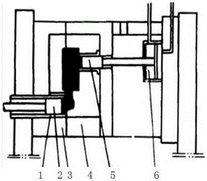
[0014] see figure 1 , the embodiment of the present invention includes:

[0015] An anti-shrinkage cavity die-casting mold for aluminum alloy parts, comprising: a fixed mold 3 and a movable mold 4, the fixed mold 3 and the movable mold 4 are arranged oppositely to form a cavity corresponding to the aluminum alloy part at the joint, the movable mold Die 4 is provided with an extrusion hole that communicates with the cavity, and an extrusion pin 5 is arranged in the extrusion hole, and a pressure chamber 1 that is con...


PUM


Abstract

The invention discloses a cavity-shrinkage-prevention die-casting mold of an aluminum alloy component. The die-casting mold comprises a fixed mold body and a movable mold body, wherein the fixed mold body and the movable mold body are oppositely arranged; a cavity corresponding to the aluminum alloy component is formed at the combining position of the fixed mold body and the movable mold body; an extrusion hole communicated with the cavity is formed in the movable mold body, and an extrusion pin is arranged in the extrusion hole; and a pressing chamber connected with the cavity is arranged on the fixed mold body, and a punch for die casting is arranged in the pressing chamber. By means of the manner, according to the cavity-shrinkage-prevention die-casting mold of the aluminum alloy component, on the basis of the principle of shrinkage cavity and shrinkage porosity generation, the extrusion pin is arranged at the position, located at the position with the large product wall thickness, of the movable mold body, and in the die-casting molding process, the aluminum alloy is solidified into the semi-solid state from the liquid state; and the extrusion pin carries out extrusion towards the product wall-thickness position, the feeding and compaction effect is achieved, the problems of product cavity shrinkage and shrinkage porosity are effectively solved, and the product quality is improved.

Description

technical field [0001] The invention relates to the field of die-casting production of auto parts, in particular to an anti-shrinkage cavity die-casting mold for aluminum alloy parts. Background technique [0002] Generally, the design of die-casting parts requires relatively simple structure and uniform wall thickness to ensure that stress cracks and internal shrinkage are as few as possible during die-casting. However, with the development trend of lightweight and highly concentrated automotive industry design , More and more products have the characteristics of complex structure, large difference in wall thickness and high performance requirements. [0003] In order to cope with the increasingly complex product structure and higher internal quality requirements, die-casting equipment and die-casting molds are also constantly improving with the times. Mold vacuum design is relatively common, and the overall internal density of die castings has also been greatly improved. ...

Claims


Application Information

Patent Timeline
Patent Type & Authority Applications(China)
IPC IPC(8): B22D17/22B22D27/09
CPCB22D17/22B22D27/09
Inventor 应悠汀张伯胥李佩婷吕鑫波许育宏
Owner 江苏宏马科技股份有限公司
Why Eureka
Try Eureka