Check patentability & draft patents in minutes with Patsnap Eureka AI!
Three-way core-pulling mechanism of injection mold
What is Al technical title?
Al technical title is built by PatSnap Al team. It summarizes the technical point description of the patent document.
A core-pulling mechanism and injection mold technology, applied in the field of injection molds, can solve the problems of slow core-pulling action of an oil cylinder, an increase in the tonnage of an injection molding machine, and an increase in manufacturing costs.
Active Publication Date: 2016-02-17
ZHEJIANG KAIHUA MOLDS
View PDF5 Cites 4 Cited by
Summary
Abstract
Description
Claims
Application Information
AI Technical Summary
This helps you quickly interpret patents by identifying the three key elements:
Problems solved by technology
Method used
Benefits of technology
Problems solved by technology
[0002] After the plastic part is injection-molded by the injection mold, if the plastic part is formed with upward inclined ribs, downward inclined ribs and side holes, the existing technology usually enlarges the cavity and the core, and then separates them in the cavity and the core. Set the oil cylinder, use the oil cylinder to directly pull the core, the cost of the oil cylinder is high, and after the cavity and the core are enlarged, the volume of the entire injection molding machine will increase, and the tonnage of the injection molding machine will increase, thereby increasing the manufacturing cost, and the core pulling action of the oil cylinder is slow. reduced productivity
Method used
Image
Click on the blue label to locate the original text in one second.
Reading with bidirectional positioning of images and text.
Examples
Embodiment Construction
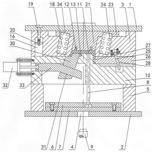
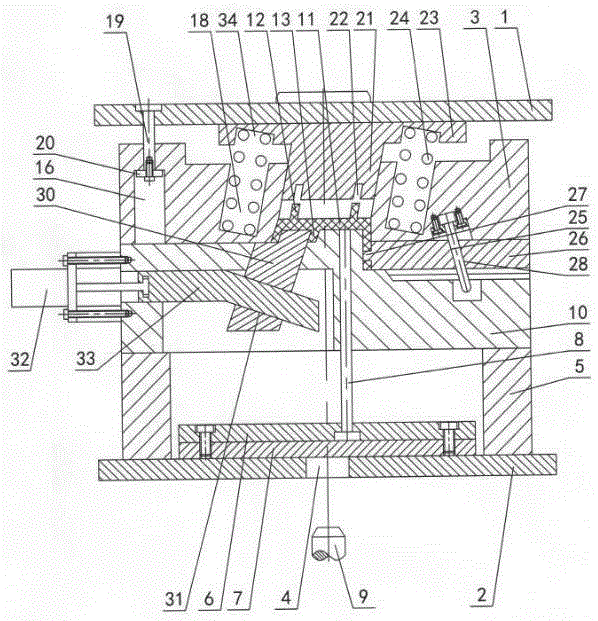
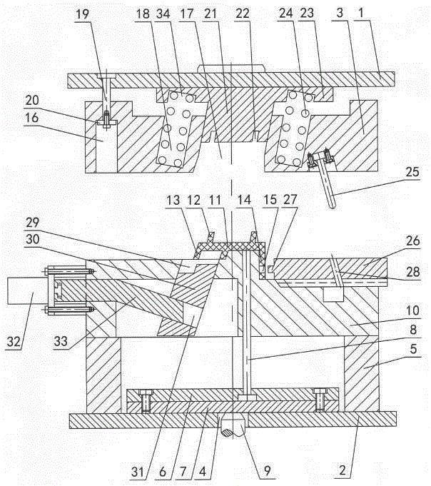
[0011] The invention relates to a three-way core-pulling mechanism of an injection mold, such as figure 1 — Figure 4 As shown, it includes an upper doubler plate 1 and a lower doubler plate 2, a cavity 3 is set under the upper doubler plate, a perforation 4 is opened in the lower doubler plate, mold feet 5 are set on the lower doubler plate, and the lower doubler plate between the mold feet An upper ejector plate 6, a lower ejector plate 7, and an ejector pin 8 are arranged on the top, and the ejector rod 9 of the injection machine passes through the perforation 4 to contact the lower ejector plate. The plastic part 11 is formed with an upper inclined rib 12, a lower inclined rib 13 and a side panel 14, and a side hole 15 is opened on the side panel. 16. The upper inclined chute 17 and the inclined spring groove 18, the fixed distance pull rod 19 is arranged under the upper double plate 1, and the fixed distance pull rod passes through the fixed distance pull groove to conne...
PUM
Abstract
A three-way core-pulling mechanism of an injection mold comprises an upper doubling plate, a lower doubling plate; the upper doubling plate is provided with a cavity, the lower doubling plate is provided with a through hole, the lower doubling plate is provided with die feet, an upper thimble plate, a lower thimble plate and a thimble, the die feet are provided with a mold core, a plastic part is arranged between the mold core and the cavity, the plastic part is provided with an upper oblique rib, a lower oblique rib and a side panel, the side panel is provided with a side hole, the three-way core-pulling mechanism is characterized in that a controlled distance kerve, an upper oblique chute and oblique spring slots are arranged in the cavity, the upper doubling plate is provided with a controlled distance pull rod connected with a controlled distance pull plate, the controlled distance pull plate is matched with the controlled distance kerve, the upper oblique chute is internally provided with an upper oblique sliding block, the lower part of the upper oblique chute is provided with an upper rib slot matched with the upper oblique rib, baffles are arranged at two sides of the upper oblique sliding block, the oblique spring slots are internally provided with oblique springs of which the upper ends contact the baffles, an oblique guide column is arranged under the cavity, the mold core is provided with a side core-pulling sliding block provided with a side lug and an oblique guide hole, the mold core is internally provided with a lower oblique chute internally provided with a lower oblique sliding block, the upper end of the lower oblique sliding block is matched with the lower oblique rib, an oblique guide slot is arranged in the lower oblique sliding block, one side of the mold core is provided with an oil pumping cylinder connected with a bent pin, and the bent pin is matched with the oblique guide slot.
Description
technical field [0001] The invention relates to an injection mold, in particular to a three-way core-pulling mechanism of an injection mold. Background technique [0002] After the plastic part is injection-molded by the injection mold, if the plastic part is formed with upward inclined ribs, downward inclined ribs and side holes, the existing technology usually enlarges the cavity and the core, and then separates them in the cavity and the core. Set the oil cylinder, use the oil cylinder to directly pull the core, the cost of the oil cylinder is high, and after the cavity and the core are enlarged, the volume of the entire injection molding machine will increase, and the tonnage of the injection molding machine will increase, thereby increasing the manufacturing cost, and the core pulling action of the oil cylinder is slow. Reduced production efficiency. Contents of the invention [0003] The purpose of the present invention is to overcome the shortcomings of the prior a...
Claims
Application Information
Patent Timeline
Application Date:The date an application was filed.
Publication Date:The date a patent or application was officially published.
First Publication Date:The earliest publication date of a patent with the same application number.
Issue Date:Publication date of the patent grant document.
PCT Entry Date:The Entry date of PCT National Phase.
Estimated Expiry Date:The statutory expiry date of a patent right according to the Patent Law, and it is the longest term of protection that the patent right can achieve without the termination of the patent right due to other reasons(Term extension factor has been taken into account ).
Invalid Date:Actual expiry date is based on effective date or publication date of legal transaction data of invalid patent.
