
Elevator shaft structure

A technology for elevator shafts and columns, applied in the field of elevators, can solve the problems of damaging villa decoration, uncompact structure, and complexity, etc., and achieve the effects of strengthening compressive strength, improving work cleanliness, and reducing space occupancy

Inactive Publication Date: 2016-02-17
ARIS CO LTD
View PDF0 Cites 17 Cited by
  • Summary
  • Abstract
  • Description
  • Claims
  • Application Information

AI Technical Summary

Problems solved by technology

[0002] With the improvement of everyone's living standards and the pursuit of high-income people's quality of life, the market for household ladders is also growing. Nowadays, the steel structure of household ladders is welded with square steel, and the glass curtain wall bracket is made on the square steel after welding. , this kind of steel structure is too complicated, on-site construction needs to be welded, it is easy to produce welding slag and damage the decoration in the villa, and it takes up too many wells, and the structure is not compact after installation.

Method used


Image

  • Elevator shaft structure
  • Elevator shaft structure
  • Elevator shaft structure

Examples


Embodiment Construction

[0029] It should be noted that, in the case of no conflict, the embodiments of the present invention and the features in the embodiments can be combined with each other.

[0030] In describing the present invention, it should be understood that the terms "center", "longitudinal", "transverse", "upper", "lower", "front", "rear", "left", "right", " The orientations or positional relationships indicated by "vertical", "horizontal", "top", "bottom", "inner" and "outer" are based on the orientations or positional relationships shown in the drawings, and are only for the convenience of describing the present invention and Simplified descriptions, rather than indicating or implying that the device or element referred to must have a particular orientation, be constructed and operate in a particular orientation, and thus should not be construed as limiting the invention. In addition, the terms "first", "second", etc. are used for descriptive purposes only, and should not be understood ...


PUM


Abstract

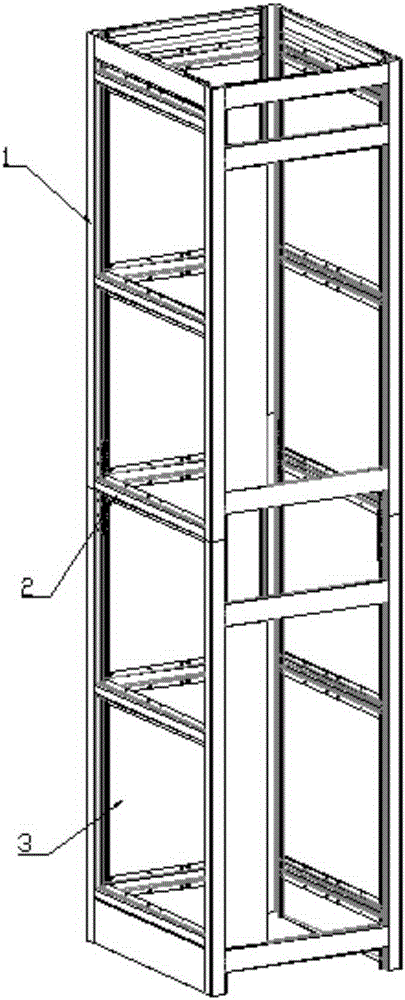
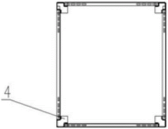
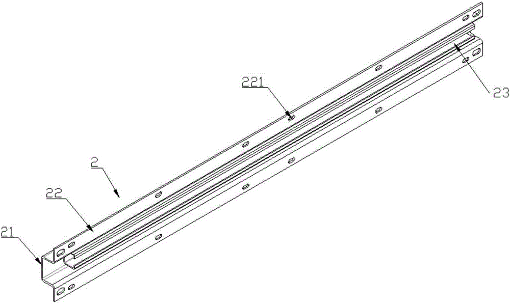
The invention provides an elevator shaft structure. The elevator shaft structure comprises four stand columns arranged in parallel and a plurality of cross beams. The four stand columns are connected in a surrounding mode to form a rectangular passage. Each stand column comprises stand column steel, wherein the two sides of the stand column steel extend outwards to form containing steel with stand column connecting holes. Each cross beam comprises supporting steel, wherein the two sides of the supporting steel extends outwards to form connecting steel, the supporting steel comprises a transverse containing cavity, a sliding rail is arranged in the transverse containing cavity, and the outer wall of the sliding rail is welded to the wall of the transverse containing cavity of the supporting steel. Every two adjacent stand columns are connected through the corresponding cross beam. The stand columns and the cross beams are connected through bolts, so that the work cleaning degree of a lap-joint shaft is improved, the stand columns and cross beams of different specifications can be selected according to the needs, and the overall space occupation rate of the shaft is effectively reduced.

Description

technical field [0001] The invention belongs to the field of elevators, in particular to an elevator shaft structure. Background technique [0002] With the improvement of everyone's living standards and the pursuit of high-income people's quality of life, the market for household ladders is also growing. Nowadays, the steel structure of household ladders is welded with square steel, and the glass curtain wall bracket is made on the square steel after welding. , This kind of steel structure is too complicated, on-site construction needs welding, it is easy to produce welding slag to damage the decoration in the villa, and it takes up too many shafts, and the structure is not compact after installation. Contents of the invention [0003] In view of this, the present invention aims to propose an elevator shaft structure to achieve the purpose of occupying a small space and being easy to install. [0004] In order to achieve the above object, technical solution of the presen...

Claims


Application Information

Patent Timeline
Patent Type & Authority Applications(China)
IPC IPC(8): B66B11/00
Inventor 李洪利成剑
Owner ARIS CO LTD
Learn More