Power transmission system

A technology of power transmission system and electric vehicle, which is applied in the direction of power unit, electric power unit, control device, etc., can solve the problems that the reducer is difficult to meet the installation space restriction requirements, the working reliability of the reducer is poor, and the structural stability of the reducer is poor. Achieve the effect of meeting the requirements of installation space constraints, improving structural stability and smooth transmission

Pending Publication Date: 2018-09-07
HUAWEI TECH CO LTD
View PDF8 Cites 6 Cited by
  • Summary
  • Abstract
  • Description
  • Claims
  • Application Information

AI Technical Summary

Problems solved by technology

However, increasing the number of teeth of the inner ring gear will increase the radial size of the reducer, making it difficult for the reducer to meet the installation space requirements of the power transmission system of electric vehicles; reducing the number of teeth of the sun gear w

Method used


Image

  • Power transmission system
  • Power transmission system
  • Power transmission system

Examples


Example Embodiment

[0048] The embodiments of the present application will be described below in conjunction with the drawings in the embodiments of the present application.

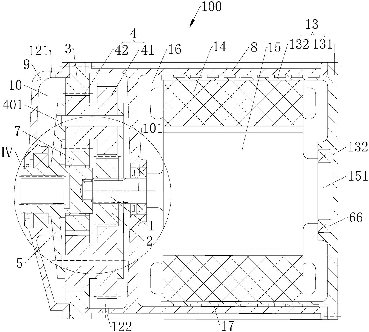
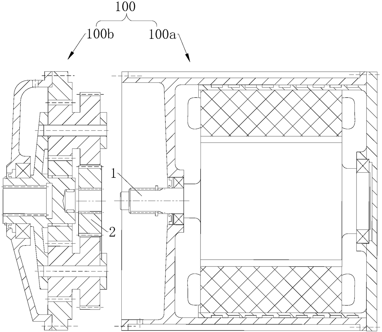
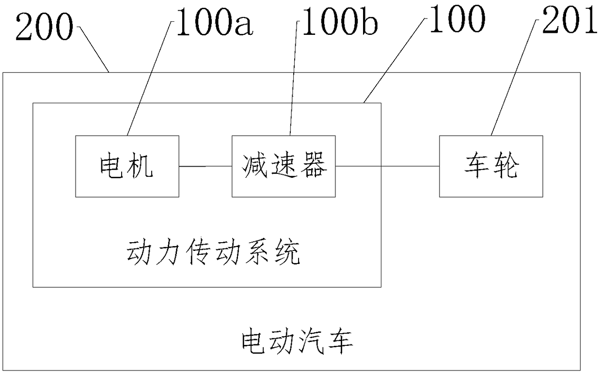
[0049] Please refer to Figure 1 to Figure 4 The embodiment of the present application provides a power transmission system 100, which may be applied to an electric vehicle 200. The power transmission system 100 includes a motor 100a and a reducer 100b. The motor 100 a includes an output shaft 1, and the axis of the output shaft 1 is a first centerline 101. The speed reducer 100b includes a sun gear 2, an inner ring gear 3, a double planetary gear 4 and a planet carrier 5. The sun gear 2 is fixedly sleeved on the outer circumference of the output shaft 1. The ring gear 3 is coaxial with the sun gear 2 and an installation space is formed between the ring gear 3 and the sun gear 2. The double planetary gear 4 is arranged in the installation space. The double planetary gear 4 includes a first gear 41 and a second gear 42 tha...


PUM


Abstract

The invention discloses a power transmission system which comprises a motor and a speed reducer. The axis of an output shaft of the motor is a first center line. The speed reducer comprises a sun gear, an inner gear ring, duplex planet gears and a planet carrier. The output shaft is fixedly sleeved with the sun gear. The inner gear ring and the sun gear are coaxial. A first gear of the duplex planet gears is engaged with the sun gear, and a second gear of the duplex planet gears is engaged with the inner gear ring. A first connecting part of the planet carrier is rotationally connected with the output shaft, so that the output shaft supports the planet carrier in the direction perpendicular to the first center line. A second connecting part of the planet carrier rotates around the first center line. A third connecting part of the planet carrier is rotationally connected with the axis position of the second gear. The output shaft drives the sun gear to rotate, so that the first gear andthe second gear synchronously rotate and revolute at the same time between the sun gear and the inner gear ring, and the second gear drives the third connecting part to rotate around the first centerline, so that a second connecting part rotates. The increase difficulty of the speed reducing ratio of the power transmission system is small.

Description

Technical field [0001] This application relates to the technical field of electric vehicles, in particular to a power transmission system. Background technique [0002] Existing electric vehicles using planetary gear transmission systems mostly use NGW planetary gear systems, that is, the output end of the motor rotor shaft is connected to the sun gear of the planetary gear reducer, and the inner ring gear is connected to the housing. , The planetary gear and the gear meshing transmission principle of the inner ring gear, and finally output the motor speed and power through the planet carrier. NGW type planetary gear reducer reduction ratio i 1H The calculation formula is: [0003] i 1H =z 2 / z 1 +1. [0004] Where z 1 Is the number of teeth of the sun gear; z 2 Is the number of teeth of the inner ring gear. [0005] In order to meet the acceleration performance and high-speed performance of electric vehicles, the development of power systems has put forward higher demands on the re...

Claims


Application Information

Patent Timeline
IPC IPC(8): B60K1/00B60K17/08
CPCB60K1/00B60K17/08
Inventor 夏公川李晶晶徐超
Owner HUAWEI TECH CO LTD
Why Eureka
Try Eureka