Spring damping delay control device for vacuum toilet related equipment

A technology of spring damping and time-delay control, which is applied to water supply devices, flushing toilets, flushing equipment with water tanks, etc. It can solve the problems of high space occupation rate, poor functionality, poor precision, etc., and achieve fewer types and quantities of parts , compact structure design and small space occupation

Active Publication Date: 2020-09-18
QINGHUAN TUODA (SUZHOU) ENVIRONMENTAL TECH CO LTD
View PDF9 Cites 12 Cited by
  • Summary
  • Abstract
  • Description
  • Claims
  • Application Information

AI Technical Summary

Problems solved by technology

[0011] The purpose of the present invention is to provide a spring damping delay control device for vacuum toilet related equipment, so as to solve the problems caused by the complex structure of the control device in the prior art, high space occupancy rate, high input cost and maintenance cost, and poor functionality. Poor and high failure rate

Method used


Image

  • Spring damping delay control device for vacuum toilet related equipment
  • Spring damping delay control device for vacuum toilet related equipment
  • Spring damping delay control device for vacuum toilet related equipment

Examples


Embodiment Construction

[0056] The content of the present invention will be further described in detail below in conjunction with specific embodiments:

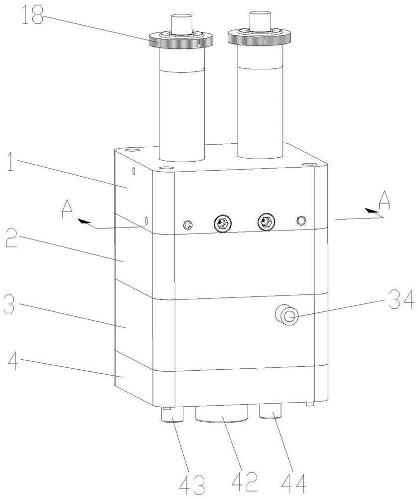
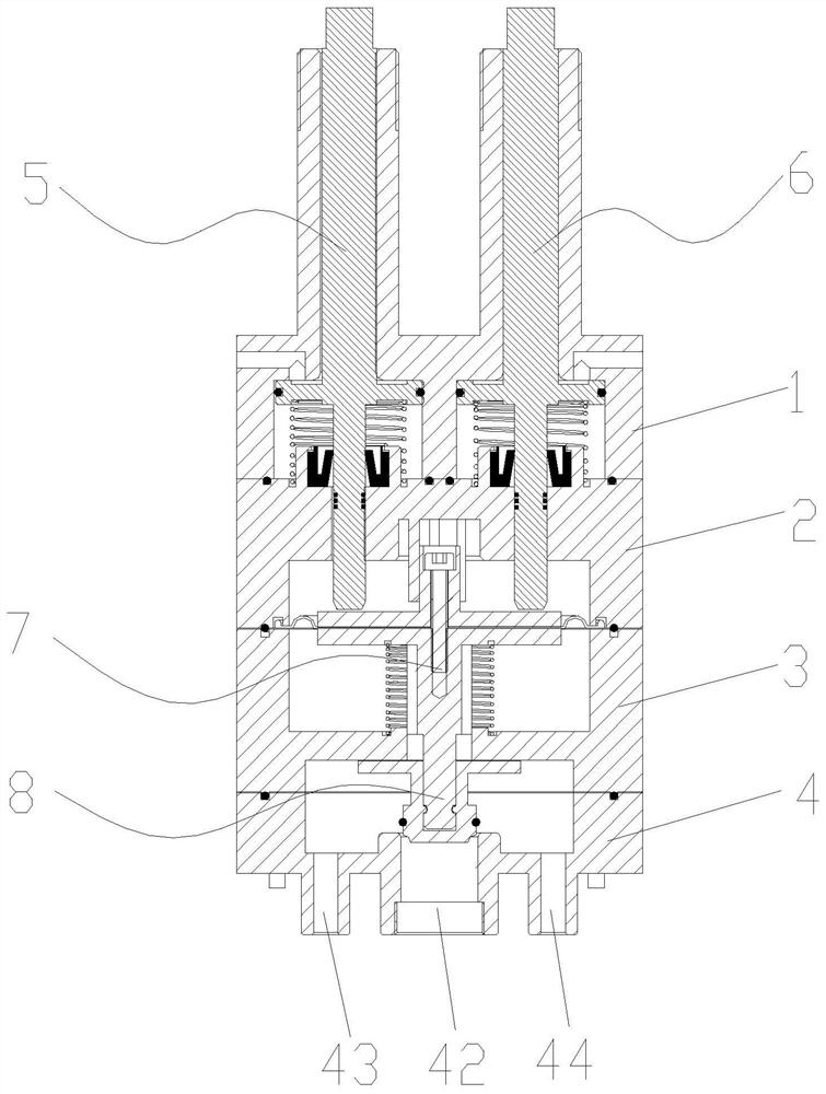
[0057] Such as figure 1 , figure 2 As shown, a spring damping delay control device for vacuum toilet related equipment, wherein vacuum toilet related equipment includes but not limited to vacuum toilets, vacuum urinals and other equipment, the present invention mainly includes input and output units, energy units, power units , Execution unit and control unit; wherein the input and output unit includes a housing, an input interface and an output interface installed on the housing, a control interface for triggering the operation of the energy unit and the control unit; the energy unit includes a large impact installed in the housing The water button assembly 5 and the small flush button assembly 6; the power unit includes a diaphragm assembly 7 installed in the housing and capable of independently controlling the movement of the piston through the larg...


PUM


Abstract

The invention relates to a spring damping delay control device for vacuum toilet related equipment. The spring damping delay control device comprises an input and output unit, an energy unit, a powerunit, an execution unit and a control unit, wherein the input and output unit comprises a shell body, an input interface and an output interface which are installed on the shell body, and a control interface used for triggering the energy unit and the control unit to work; the energy unit comprises a large flushing button assembly and a small flushing button assembly; the power unit comprises a diaphragm assembly capable of achieving piston movement; the execution unit comprises a slide valve assembly connected with the diaphragm assembly; and the control unit comprises a needle valve assemblyand a one-way valve assembly. The spring damping time delay control device is adopted for control, gas pressure difference adopted abroad for transduction is avoided, other control modes and energy types such as an electromagnetic valve, a battery, solar energy and wind energy are not needed, and the input cost is low; and the structural design is compact, the space occupancy rate is small, the types and number of parts are small, and reliability is high.

Description

Technical field [0001] The invention relates to the technical field of vacuum toilet related equipment, in particular to a spring damping delay control device for vacuum toilet related equipment. Background technique [0002] The basic working principle of the control device is to switch between partial vacuum and atmospheric pressure in the controller chamber to realize the opening (working state) and closing (non-working state) of the vacuum drain valve and flushing valve; it has this structure type The control device is used to control the flushing or (and) the sewage process of the vacuum toilet related equipment. The control process of the control device is to manipulate the vacuum drain valve to discharge the feces or other gas-liquid solids in the vacuum toilet from the vacuum toilet related equipment to the vacuum collection device (such as the intermediate container, the following vacuum waste water tank) or the vacuum sewer , At the same time, the flush valve is contro...

Claims


Application Information

Patent Timeline
Patent Type & Authority Applications(China)
IPC IPC(8): E03D5/00E03D5/09E03D11/00E03F1/00
CPCE03D5/00E03D5/09E03D11/00E03F1/006
Inventor 崔利兴
Owner QINGHUAN TUODA (SUZHOU) ENVIRONMENTAL TECH CO LTD
Why Eureka
Try Eureka