Photoresist liquid feeding device and modified set using same

A technology of supplying device and photoresist, which is applied to optics, electrical components, opto-mechanical equipment, etc., can solve the problems of small transportation volume, high purchase cost, and high cost of photoresist liquid products, and avoid supply interruption, concentration Stabilizing effect

Inactive Publication Date: 2007-03-14
TOKYO OHKA KOGYO CO LTD
View PDF2 Cites 11 Cited by
  • Summary
  • Abstract
  • Description
  • Claims
  • Application Information

AI Technical Summary

Problems solved by technology

[0015] Not only is the purchase cost high for such a small dedicated container, but also the cost of photoresist liquid products is high due to the trouble and expense of container management and recycling.
In addition, whe

Method used


Image

  • Photoresist liquid feeding device and modified set using same
  • Photoresist liquid feeding device and modified set using same
  • Photoresist liquid feeding device and modified set using same

Examples


no. 1 approach

[0110]

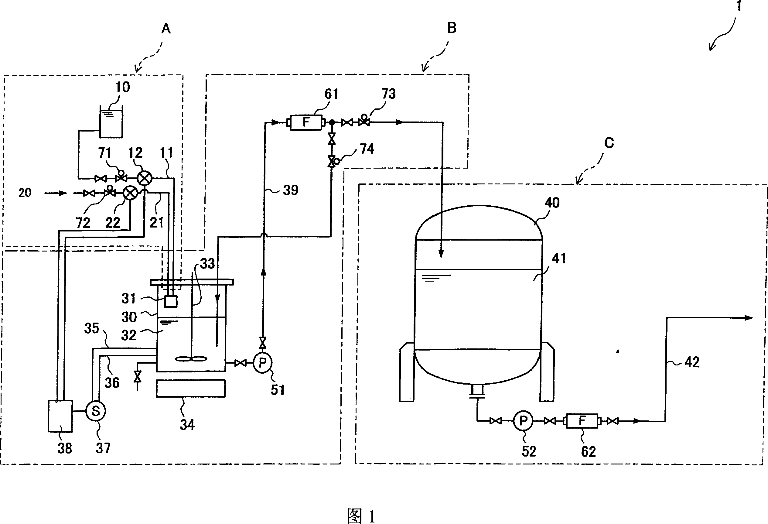
[0111] FIG. 1 is a diagram showing a photoresist solution supply device 1 according to a first embodiment of the present invention. The photoresist solution supply device 1 of the present embodiment has an introduction part A for introducing a high-concentration raw material solution 10, a mixing part B for mixing and stirring the raw material solution 10 introduced into the introduction part A and a solvent 20, and a mixing and stirring part B for mixing and stirring the raw material solution 10 introduced into the introduction part A, and supplying the raw material liquid 10 and the solvent 20 through mixing and stirring. The supply part C of the photoresist solution for the product obtained by mixing and stirring in the part B to adjust the concentration.

[0112] The introduction part A is mainly composed of a raw material liquid introduction line 11 , a raw material liquid flow meter 12 , a solvent introduction line 21 and a solvent flow meter 22 . The mixing p...

no. 2 approach

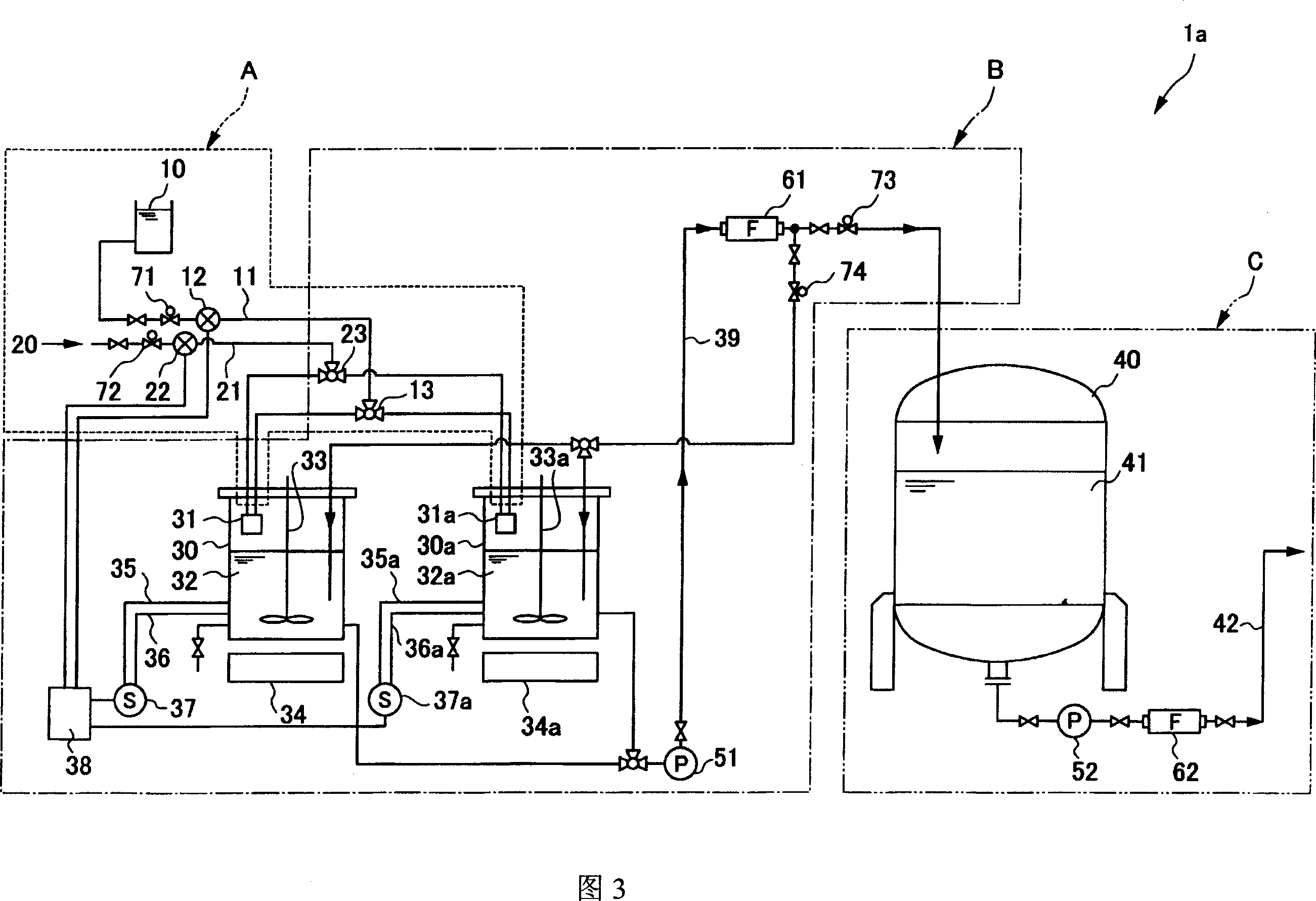
[0208] FIG. 3 is a schematic structural view of a photoresist solution supply device 1 a according to a second embodiment of the present invention. The resist solution supply device 1 a is mainly different from the first embodiment in that a mixing part B thereof has a plurality of mixing tanks.

[0209] [Import Department]

[0210] The structure of the introduction part A related to this embodiment is the same as that of the first embodiment, but the mixing part B has a plurality of mixing tanks 30, 30a. In each of these mixing tanks 30, 30a, the raw material liquid introduction line 11 and the solvent introduction line 21 separated by the three-way valve 13, 23 are connected together. In addition, in Fig. 3, the mixing part B has 2 blending tanks, but there is no limit to the number of blending tanks, the raw material liquid introduction pipeline and the solvent introduction pipeline can only be divided into the number of blending tanks, and combined into each Blending tan...

no. 3 approach

[0222] FIG. 4 is a diagram showing a photoresist solution supply device in a third embodiment of the present invention.

[0223] The photoresist solution supply device 1b has a first mixing tank 30 for coarsely adjusting the concentration of the photoresist solution and a second mixing tank 30b for finely adjusting the concentration of the mixed solution 32 adjusted by the first mixing tank 30 The mixing and stirring part B. In addition, since the introduction part A and the supply part C have the same structure, description is abbreviate|omitted.

[0224] [mixing and stirring department]

[0225] The mixing part B has the 1st mixing tank 30 and the 2nd mixing tank 30b. The structure of each mixing tank is the same as that of the first embodiment, and the same structure is represented by adding b to the same reference numeral.

[0226] [Operation of the mixing section]

[0227] In this embodiment, after the concentration of the mixed liquid is roughly adjusted in the first...


PUM


Abstract

Provided is a photoresist liquid feeding device capable of reducing the cost of the feeding of photoresist liquid and avoiding the using of the expensive minitype special purpose container which is directly connected, in statu quo, to the current LCD panel production line, and thus reducing the cost of the feeding of photoresist liquid in the mass. In the photoresist liquid feeding device, at least one of the concentration and the viscosity of the liquid inside of the blending tank is determined, diluting control is executed by adjusting the injection rate of the raw material liquid and the solvent based on the determined results, at the same time, the product obtained by diluting control is stored in the buffer tank for a certain time with photoresist liquid so that the product is stable.

Description

technical field [0001] The invention relates to a photoresist solution supply device and a transformation kit for obtaining the photoresist solution supply device. More specifically, it relates to a device for obtaining a photoresist solution of a predetermined concentration from a high-concentration raw material solution, and supplying the product photoresist solution, and a remodeling kit for obtaining the photoresist solution supply device. Background technique [0002] In liquid crystal display panels (hereinafter referred to as LCD panels) such as color televisions, personal computers, and pachinko machines, TFT liquid crystal displays formed by a thin film transistor (hereinafter referred to as TFT) liquid crystal method are becoming mainstream. This TFT liquid crystal display employs a technology called an active matrix method, and has an array substrate on which thin film transistors are mounted, a color filter substrate for coloring, and a liquid crystal cell in whi...

Claims


Application Information

Patent Timeline
IPC IPC(8): G03F7/16
CPCG03F7/16G03F7/3092G03F7/70608H01L21/6715
Inventor 森尾公隆青木知三郎长谷川透
Owner TOKYO OHKA KOGYO CO LTD
Why Eureka
Try Eureka