Exhaust valve component and linear compressor

A technology of linear compressors and exhaust valves, which is applied to pump components, mechanical equipment, machines/engines, etc., and can solve problems such as inability to effectively seal cylinders

Inactive Publication Date: 2016-02-17
QINGDAO HAIER SMART TECH R & D CO LTD
View PDF4 Cites 3 Cited by
  • Summary
  • Abstract
  • Description
  • Claims
  • Application Information

AI Technical Summary

Problems solved by technology

[0003] In view of this, in order to solve the problem in the prior art that the cylinder cannot be effectively s

Method used


Image

  • Exhaust valve component and linear compressor
  • Exhaust valve component and linear compressor
  • Exhaust valve component and linear compressor

Examples


Embodiment Construction

[0019] The following description and drawings illustrate specific embodiments of the invention sufficiently to enable those skilled in the art to practice them. Portions and features of some embodiments may be included in or substituted for those of other embodiments. The scope of embodiments of the present invention includes the full scope of the claims, and all available equivalents of the claims. These embodiments of the present invention may be referred to herein, individually or collectively, by the term "invention", which is for convenience only and is not intended to automatically limit the application if in fact more than one invention is disclosed The scope is any individual invention or inventive concept.

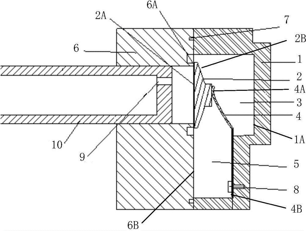
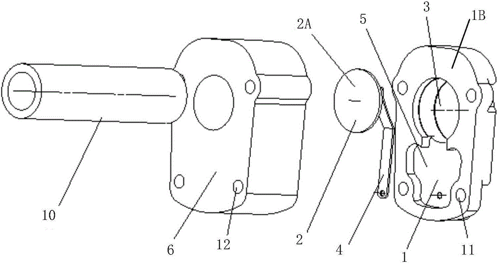
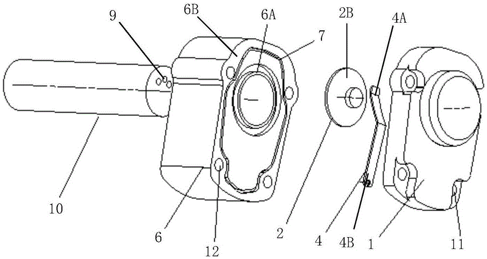
[0020] Refer below Figure 1 ~ Figure 3 A discharge valve assembly and a linear compressor according to an embodiment of the present invention are described in detail.

[0021] Such as figure 1 As shown, an exhaust valve assembly includes: a cylinder head 1 wi...


PUM


Abstract

The invention discloses an exhaust valve component and a linear compressor. The exhaust valve component comprises a cylinder head with an exhaust chamber and an exhaust valve piece which is arranged in the exhaust chamber and is connected with the cylinder head through an elastic component, wherein the elastic component is rod-shaped or slice-shaped. Adopting the exhaust valve can achieve the benefits that the situation that an air cylinder cannot be effectively sealed due to the deformation or decentration of a compression spring is avoided; the device is assembled more easily; and the elastic component is made of a highly elastic resilience material, so that the compression loss is reduced, the exhaust is easier, and the performance and production efficiency of the linear compressor are improved.

Description

technical field [0001] The invention belongs to the mechanical field, and in particular relates to an exhaust valve assembly and a linear compressor. Background technique [0002] A linear compressor is a device that inhales and compresses refrigerant gas when the piston reciprocates linearly in the cylinder. In the prior art, since the compression spring is used for sealing, the spring is bent and deformed during the spring compression process, and the center of the exhaust valve plate always deviates from the center of the cylinder, resulting in the deviation of the sealing end face of the exhaust valve plate. Inability to effectively seal the cylinder. The deformation force of the compression spring is relatively large, so that when the piston compresses the refrigerant, a large input power must be input, and only when a large exhaust pressure is generated can it be exhausted. This is why the linear compressor does not reach the top dead center. An important reason for ...

Claims


Application Information

Patent Timeline
IPC IPC(8): F04B39/10F04B39/12
Inventor 赵志强李衡国闫赛娜宋斌李孟成许升
Owner QINGDAO HAIER SMART TECH R & D CO LTD
Why Eureka
Try Eureka