

A wind cabinet layered water retaining device
The technology of a water blocking device and a wind cabinet is applied in the field of a layered water blocking device and a water blocking device of the wind cabinet, which can solve the problems of increasing material consumption and increasing the resistance of the water blocking board, so as to reduce energy consumption and improve the efficiency of water collection. Effect
- Summary
- Abstract
- Description
- Claims
- Application Information
AI Technical Summary
Problems solved by technology
Method used
Image

Examples
Embodiment 1
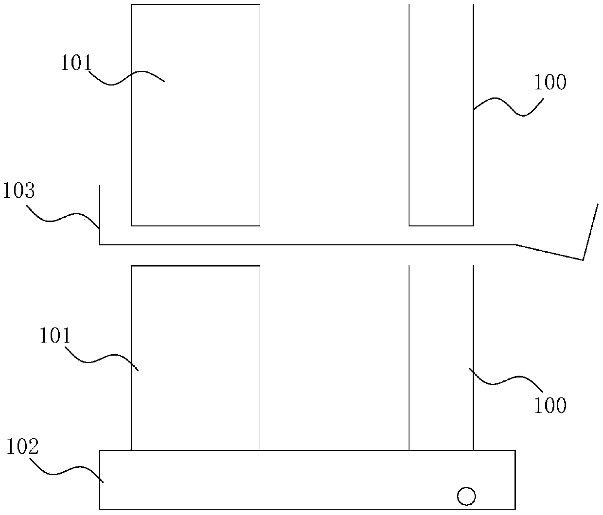
[0044] Such as Figure 1~3 As shown, in this embodiment, the present invention provides a layered water-retaining device for wind cabinets, including a bottom drain pan 102 at the bottom and a water tank vertically arranged on the drain pan with a height corresponding to the height of the air conditioner surface cooler 101. The water baffle assembly 100 is provided with at least one middle drain pan 103 parallel to the bottom drain pan 102 on the water baffle assembly 100 .
[0045] During the working process, the condensed water collected by the water baffle assembly 100 above the uppermost middle drain pan 103 flows along the water baffle assembly 100 into the uppermost middle drain pan 103, and the water retaining water below the uppermost drain pan The condensed water collected by the plate assembly 100 flows along the baffle assembly 100 to the intermediate drain pan 103 of the next stage, and so on. The condensed water collected by the water plate assembly 100 flows alo...
Embodiment 2
[0068] Such as Figure 4 As shown, the technical solution of this embodiment is basically the same as that of Embodiment 1. The main difference is that the structure of the first water tank is different. In this embodiment, the first water tank includes a first water tank plate vertically connected to the first shielding surface 200 201, and the second water tank plate 202 arranged at the end of the first water tank plate 201 away from the first shielding surface 200.
[0069] The first water tank plate 201 and the second water tank plate 202 form a groove-shaped water holding space, and the water is located at the bottom of the water holding space under the action of wind force to prevent water from spreading and overflowing.
[0070] The first tank plate 201 and / or the second tank plate 202 gradually widens from an end away from the bottom drain pan (or a middle drain pan, the same below, not shown in the figure) to an end close to the bottom drain pan.
[0071] The moistur...
Embodiment 3
[0074] Such as Figure 5 As shown, the technical solution of this embodiment is basically the same as that of Embodiment 2, the main difference is that the structure of the first water tank is different. In this embodiment, the first water tank includes a first water tank plate vertically connected to the first shielding surface 300 301, and the second flume plate (not shown in the figure) arranged at the end of the first flume plate 301 away from the first shielding surface 300, also includes a third flume plate 302 arranged parallel to the first flume plate 301, the first The water tank plate 301 is provided with a water hole 303 that allows the liquid collected on the first water tank plate 301 to pass through the first water tank plate 301 and attach to the third water tank plate 302 .
[0075] In this embodiment, the water hole 303 is located in the middle of the vertical direction of the first water tank plate 301, the third water tank plate 302 is arranged at one end cl...
PUM
 Abstract
Description
Claims
Application Information