
A low-loss large effective area single-mode optical fiber and its optical fiber preform manufacturing method

An effective area, single-mode optical fiber technology, applied in the direction of cladding optical fiber, manufacturing tools, optical waveguide light guide, etc., can solve the problem of increasing process complexity and manufacturing cost, unstable fiber loss and cut-off wavelength, and reducing product quality stability, etc. problem, to achieve the effects of low loss, low macrobending loss, and low fiber loss

Active Publication Date: 2018-06-19
ZHONGTIAN TECH ADVANCED MATERIALS CO LTD +1
View PDF11 Cites 0 Cited by
  • Summary
  • Abstract
  • Description
  • Claims
  • Application Information

AI Technical Summary

Problems solved by technology

This design is very difficult to implement directly on VAD and OVD equipment, usually using PCVD, POD outsourcing or doped casing technology, which greatly increases process complexity and manufacturing costs
[0006] Reference CN103955020A proposes a design and process suitable for mass production of various processes. This design has a core area, an isolation area, a ditch area, an outsourcing area, and a central depression. Using this process, a low-loss fiber with better performance can be produced. Large effective area optical fiber, but in the process of manufacturing optical fiber preform by two-step method, especially in the process of manufacturing optical fiber preform by VAD+OVD process, due to the diffusion of fluorine-doped elements, the loss and cut-off wavelength of the produced optical fiber are different. Stable, which greatly increases the process complexity and reduces the stability of product quality

Method used


Image

  • A low-loss large effective area single-mode optical fiber and its optical fiber preform manufacturing method
  • A low-loss large effective area single-mode optical fiber and its optical fiber preform manufacturing method
  • A low-loss large effective area single-mode optical fiber and its optical fiber preform manufacturing method

Examples


Embodiment Construction

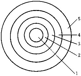
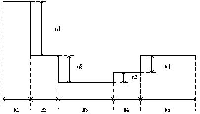
[0030] Refer to attached Figure 1~3 , a single-mode optical fiber with low loss and large effective area, its effective area at 1550nm is 100-200μm 2 , the cut-off wavelength of the optical cable is less than 1500nm, and the optical fiber includes the core area 1, the isolation area 2, the ditch area 3, the protection area 4 and the outer cladding area 5 from the center to the periphery in sequence, where:

[0031] a) Core region 1: a radius R1 extending outward from the center, the range of R1 is 4-10 μm, and its typical value is 6.0-9.0 μm. The range of refractive index difference in this area is 0-0.3%, and the typical value is 0.1%-0.2%.

[0032] b) Isolation region 2: extending outward from R1, the thickness is R2, the range of R2 is 2-21 μm, and its typical value is 5-10 μm. The range of refractive index difference in this area is -0.005% to 0.05%, and the typical value is 0 to 0.005%.

[0033]c) Trench region 3: extending outward from R1+R2, the thickness is R3, the...


PUM

PropertyMeasurementUnit
areaaaaaaaaaaa
dispersion valueaaaaaaaaaa
areaaaaaaaaaaa

Abstract

The invention relates to a low-loss large-effective-area single-mode optical fiber and an optical fiber preform manufacturing method thereof. The optical fiber preform manufacturing method is an optical fiber preform manufacturing process, and an optical fiber preform designed and manufactured by adopting the process has the advantages of having low 1550 nm wavelength loss and large effective area and can be suitable for long-distance transmission. In addition, the low-loss large-effective-area optical fiber produced by adopting the process has the advantages of having good parameter stability and low 1550 nm wavelength loss. The effective area of the optical fiber with 1550 nm wavelength is 100-200 square micrometers, the cutoff wavelength of an optical cable is smaller than 1500 nanometers, and the optical fiber sequentially comprises a fiber core area, an isolation area, a ditch area, a protection area and a cladding area from center to periphery.

Description

technical field [0001] The invention relates to a low-loss large effective area single-mode optical fiber and a method for manufacturing the optical fiber preform. The optical fiber preform designed and manufactured by this process has the characteristics of low loss at 1550nm wavelength and large effective area, and can be used in long-distance Transmission; at the same time, the low loss and large effective area optical fiber produced by this process has the characteristics of good parameter stability and low macrobending loss. Background technique [0002] In high-speed long-distance optical communication systems, the deterioration of signal-to-noise ratio and the nonlinear effect of optical fiber will be the main factors restricting the communication distance. Increasing the effective area of ​​the fiber, reducing the loss of the fiber, and improving the dispersion of the fiber are the main ways to overcome these two constraints. Reducing fiber loss can slow the rate at...

Claims


Application Information

Patent Timeline
Patent Type & Authority Patents(China)
IPC IPC(8): G02B6/02C03B37/018
CPCC03B37/018G02B6/02019
Inventor 汤明明沈一春钱宜刚
Owner ZHONGTIAN TECH ADVANCED MATERIALS CO LTD
Learn More