
Projector and its projection lens

A technology of projection lens and projection mirror, which is applied in installation, optics, instruments, etc., and can solve the problems of many internal lenses, cost, and heavy weight

Inactive Publication Date: 2017-06-27
健翔光学股份有限公司
View PDF7 Cites 0 Cited by
  • Summary
  • Abstract
  • Description
  • Claims
  • Application Information

AI Technical Summary

Problems solved by technology

[0003] As a result, the existing short-focus projection lens is not only bulky and heavy, but cannot achieve the miniaturized and lightweight design advocated today, but also because the internal lenses are both heavy and heavy, so it takes a long time to manufacture. It takes a lot of time to assemble, and its material cost is also more expensive
[0004] And in order to improve the above-mentioned shortcoming, then some industry develops a kind of rear-projection type projector, promptly utilizes reflective mirror to reflect the image light beam of projector inside to be transmitted to the imaging plane, but this kind of model is because there is no focusing function, in the The setting can only be set at a fixed distance from the imaging surface, and the setting position cannot be changed according to different projection environments, which greatly reduces its applicability
Therefore, based on the above, it can be known that the optical design of known projectors and projection lenses is still not perfect, and there is room for improvement

Method used


Image

  • Projector and its projection lens
  • Projector and its projection lens
  • Projector and its projection lens

Examples


Embodiment Construction

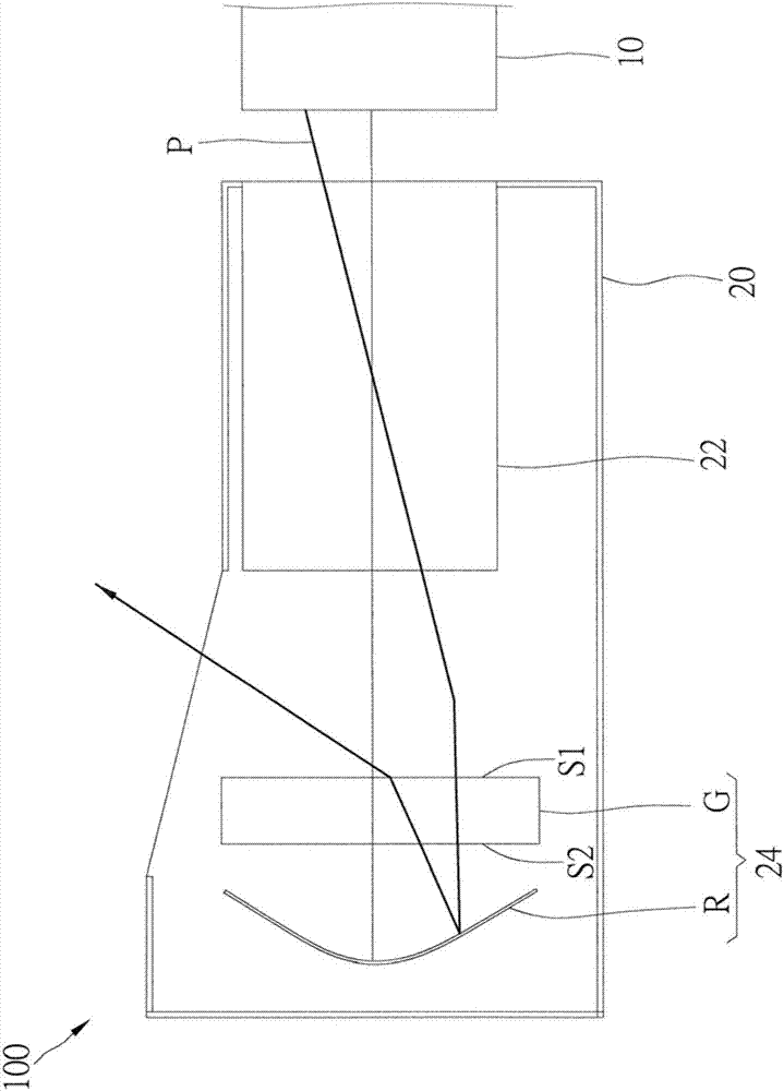
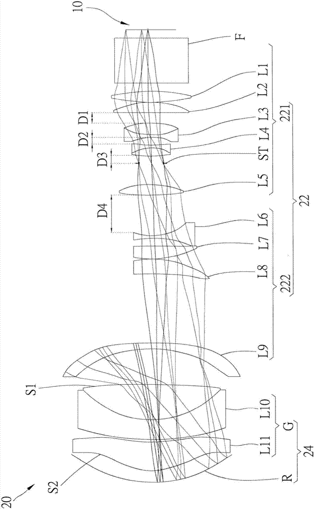
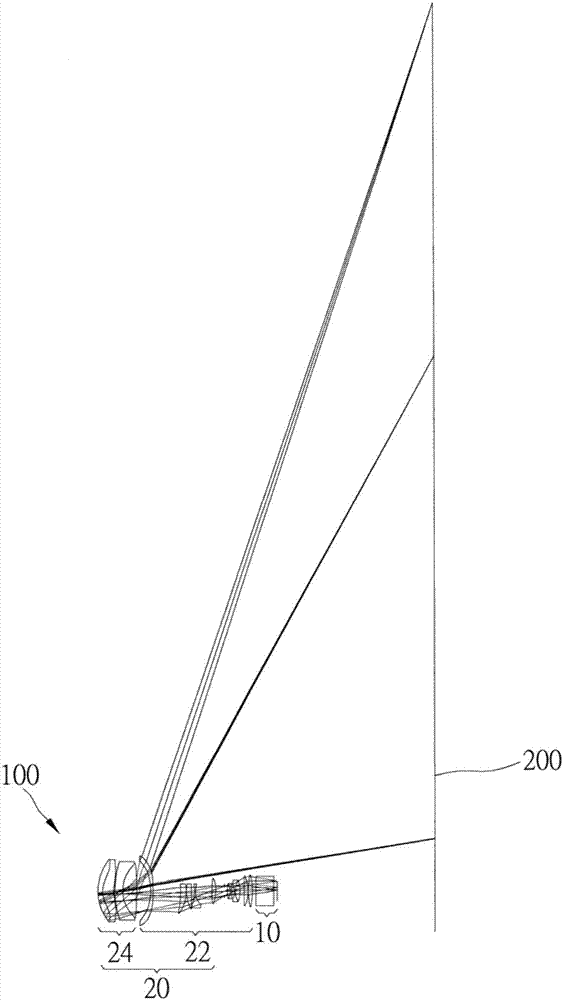
[0030] In order to illustrate the present invention more clearly, a preferred embodiment is given and detailed description is as follows in conjunction with the drawings, please refer to Figure 1 to Figure 3 Shown is a projector 100 according to a preferred embodiment of the present invention, which includes an image light source generating device 10 and a projection lens 20 . The image light source generating device 10 is used to read image information from an image source, and has a prism F, and generates a corresponding image light beam P passing through the prism F according to the read image information. The projection lens 20 is used for receiving the image light beam P and projecting it to an imaging surface after undergoing optical processing with a predetermined effect. The projection lens 20 includes a relay optical system 22 and a projection optical system 24 sequentially arranged from a side close to the image light source generating device 10 to a side far away f...


PUM


Abstract

The invention relates to a projector and its projection lens, including an image light source generating device and a projection lens. The projection lens includes a relay optical system and a projection optical system; the relay optical system includes a focusing optical group and a condensing optical group, and the focusing optical group and the condensing optical group respectively include at least one lens; in addition , the focusing optical group can move between the converging optical group and the image light source generating device; the projection optical system includes a projection mirror group and a reflector, and the projection mirror group is located between the reflector and the relay optical system Between, when the image light source generating device generates the image light beam, the image light beam passes through the relay optical system, penetrates the projection mirror group, reflects through the reflector and reversely passes through the projection mirror group , projected onto the image plane.

Description

technical field [0001] The invention relates to an optical projection device; in particular, it refers to a projector and a projection lens thereof. Background technique [0002] With the advancement of video technology, projectors are becoming more and more popular, and the projection lens used to clearly present images on the screen is one of the core components. With the limitation of the use of space, in order to achieve a clear projection effect in a small space, the projection lens of the projector is gradually designed in the direction of a short-focus projection lens, but in order to have a good projection effect in a short distance, short Focal lenses usually use a large number of lenses with large volume to achieve the effect of short focal length and high optical power. [0003] As a result, the existing short-focus projection lens is not only bulky and heavy, but cannot achieve the miniaturized and lightweight design advocated today, but also because the interna...

Claims


Application Information

Patent Timeline
Patent Type & Authority Patents(China)
IPC IPC(8): G03B21/14G03B21/28G02B7/04
Inventor 林伊柔吴欣颖
Owner 健翔光学股份有限公司
Learn More