
Ventilated moistureproof switch cabinet

A switchgear and cabinet body technology, applied in the field of ventilated and moisture-proof switchgear, can solve the problems of ineffective dehumidification, single cooling device of switchgear, personal danger, etc., and achieve improved cooling and dehumidification efficiency, good cooling and dehumidification effect, and automation high effect

Active Publication Date: 2016-02-17
STATE GRID CORP OF CHINA +1
View PDF4 Cites 27 Cited by
  • Summary
  • Abstract
  • Description
  • Claims
  • Application Information

AI Technical Summary

Problems solved by technology

Switchgears are almost always used in electrical equipment companies or machinery factories, and the electronic module units in the switchgear will generate a lot of heat during work, whether in winter or summer, heat will be generated, especially in the switchgear placed in the production workshop in summer, Due to the high temperature of the workshop itself, the temperature inside the switchgear rises after a period of operation. After a long period of operation, the switchgear may be damaged, the service life will be shortened, and there may be circuit hazards, fires, and personal dangers.
The switchgear is placed outdoors or in an environment without temperature and humidity adjustment. When the switchgear is working in an environment with high temperature and high humidity, it is also prone to work failures.
The traditional switch cabinet heat dissipation device is relatively simple, and the heat dissipation holes are directly opened on the switch cabinet body. The heat dissipation effect is poor and the heat dissipation is relatively slow. Faulty, short service life

Method used


Image

  • Ventilated moistureproof switch cabinet
  • Ventilated moistureproof switch cabinet
  • Ventilated moistureproof switch cabinet

Examples


Embodiment Construction

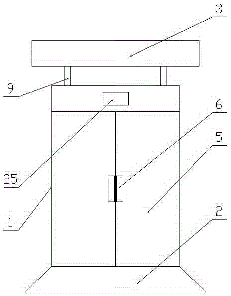
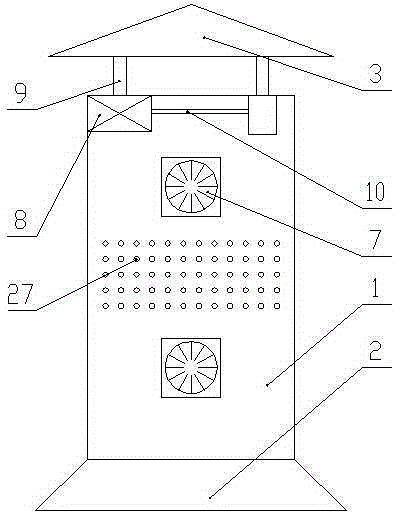
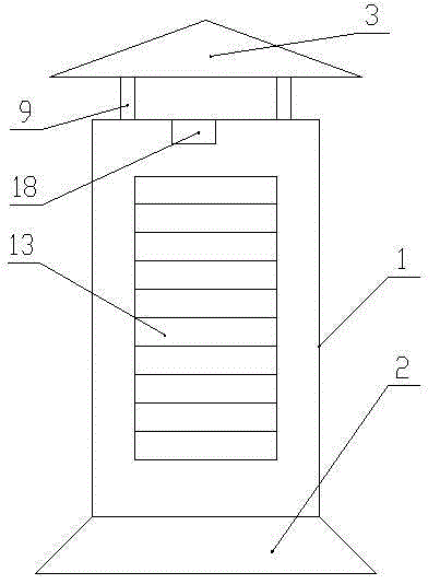
[0019] Such as Figure 1 to Figure 6 As shown, the ventilated and moisture-proof switch cabinet includes a cabinet body 1, a base 2 and a top cover 3. The cabinet body 1 is a rectangular parallelepiped structure, the base 2 is a square prism structure, and the top cover 3 is a triangular prism structure. The cabinet body 1 is installed on The top of the base 2, the top cover 3 is located on the top of the cabinet 1, a hydraulic jacking device is provided between the top cover 3 and the top of the cabinet 1, and a number of ventilation holes 4 are opened on the top of the cabinet 1, and the ventilation holes 4 are distributed along a rectangular array. The front end of the cabinet body 1 is equipped with a double door 5, the middle part of the double door body 5 is provided with a handle 6, the left side of the cabinet body 1 is provided with two cooling fans 7, and the two cooling fans 7 are arranged up and down, and the right side of the cabinet body 1 is provided with Ventil...


PUM


Abstract

The invention provides a ventilated moistureproof switch cabinet comprising a cabinet body, a base and a top cover, wherein the cabinet body is in a cuboid structure; the base is in a quadrangular frustum pyramid; the top cover is in a triangular prism structure; the cabinet body is arranged on the top of the base; the top cover is positioned on the top of the cabinet body; a hydraulic jacking device is arranged between the top cover and the cabinet body; a plurality of ventilation holes are formed in the top of the cabinet body and are distributed along a rectangular array; a double-opening door is formed in the front end of the cabinet body; two cooling fans are arranged on the left side surface of the cabinet body and are distributed in an up-down manner; a ventilation and cooling mechanism is arranged on the right side surface of the cabinet body; a control system is arranged in the cabinet body; a dust prevention filtering net is positioned at the inner side of the ventilation and cooling mechanism on the right side surface of the cabinet body; a plurality of cooling holes are formed between the two cooling fans on the left side surface of the cabinet body. The ventilated moistureproof switch cabinet is good in cooling and moistureproof effects, reliable to work, long in service life and capable of achieving automatic cooling and moistureproof effects.

Description

technical field [0001] The invention belongs to the technical field of electrical equipment, and in particular relates to a ventilation and moisture-proof switchgear. Background technique [0002] The switch cabinet is a kind of electrical equipment. The outside line of the switch cabinet first enters the main control switch in the cabinet, and then enters the sub-control switch. Each branch is set according to its needs. The main function of the switchgear is to open and close, control and protect electrical equipment during the process of power generation, transmission, distribution and power conversion in the power system. Switchgears are almost always used in electrical equipment companies or machinery factories, and the electronic module units in the switchgear will generate a lot of heat during work, whether in winter or summer, heat will be generated, especially in the switchgear placed in the production workshop in summer, Due to the high temperature of the workshop...

Claims


Application Information

Patent Timeline
IPC IPC(8): H02B1/56H02B1/28H02B1/30
CPCH02B1/28H02B1/30H02B1/565
Inventor 李廷辉王红新王永军
Owner STATE GRID CORP OF CHINA
Learn More