Self-checking system and self-checking method for cascaded multilevel converter
A cascaded multi-level, self-test system technology, applied in the measurement of electrical variables, the conversion of irreversible DC power input to AC power output, and the conversion of AC power input into DC power output, etc., can solve the problem of inability to measure insulation resistance and Calculation and other issues
- Summary
- Abstract
- Description
- Claims
- Application Information
AI Technical Summary
Problems solved by technology
Method used
Image
Examples
Embodiment 1
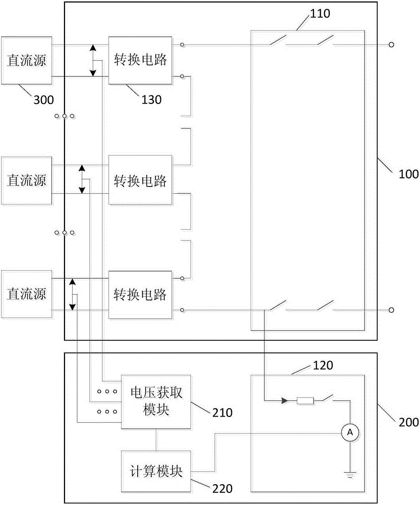
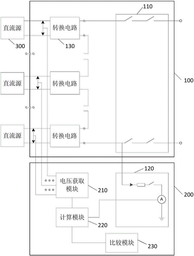
[0047] figure 1 It is a schematic structural diagram of the self-test system of the cascaded multilevel converter provided by Embodiment 1 of the present invention Figure 1 . Such as figure 1 As mentioned above, the self-checking system of the cascaded multilevel converter provided in Embodiment 1 of the present invention includes the cascaded multilevel converter 100 and the self-checking device 200, and the cascaded multilevel converter 100 includes at least two cascaded A conversion circuit 130 , the self-test device 200 includes at least one current detection circuit 120 , a voltage acquisition module 210 and a calculation module 220 .
[0048] Specifically, in the above-mentioned at least two conversion circuits 130, the conversion circuit 130 may or may not have a built-in output filter circuit. When the conversion circuit 130 has built-in output filters, the external filter circuit may no longer be provided. , otherwise, it is preferable to add a filter circuit. In...
Embodiment 2
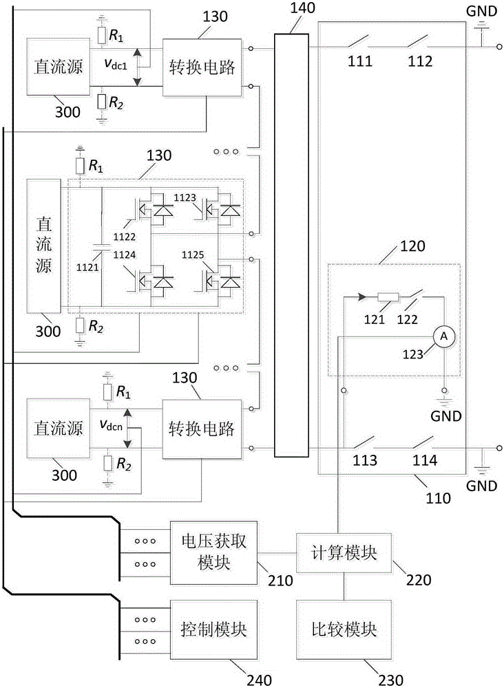
[0056] image 3 It is a schematic circuit diagram of the self-test system of the cascaded multilevel converter provided in the second embodiment of the present invention, as shown in image 3 As shown, at least two conversion circuits 130 in the system include: a first capacitor 1121, a first switching tube 1122, a second switching tube 1123, a third switching tube 1124 and a fourth switching tube 1125;
[0057] The first end of the first switch tube 1122 is electrically connected to the first end of the second switch tube 1123, the first end of the first capacitor 1121 and the positive pole of the corresponding DC source 300 respectively, and the second end of the first switch tube 1122 is connected to the positive electrode of the corresponding DC source 300. The first end of the third switch tube 1124 is electrically connected and serves as the first output end of the conversion circuit 130, and the second end of the second switch tube 1123 is electrically connected to the ...
Embodiment 3
[0071] Referring to the above-mentioned embodiments, in the technical solution of the present invention, the control module can control the conduction or cut-off of each switch tube in each conversion circuit 130, and divide the working state of the cascaded multilevel converter into the first conduction state and the second conduction state. Two conduction states. It should be noted that each switch in the switch group module 110 is in a normally-off state when the self-test system performs self-test.
[0072] Figure 5 It is an equivalent circuit when the cascaded multilevel converter provided by Embodiment 3 of the present invention is in the first conduction state. Also refer to image 3 , the detection current in the cascaded multilevel converter will flow from the second output end of the first conversion circuit 130 into the first output end of the second conversion circuit in the first conduction state, and pass through each conversion circuit 130 in turn , finally ...
PUM
 Abstract
Description
Claims
Application Information
 - R&D
- Intellectual Property
- Life Sciences
- Materials
- Tech Scout
- Unparalleled Data Quality
- Higher Quality Content
- 60% Fewer Hallucinations
Browse by: Latest US Patents, China's latest patents, Technical Efficacy Thesaurus, Application Domain, Technology Topic, Popular Technical Reports.
© 2025 PatSnap. All rights reserved.Legal|Privacy policy|Modern Slavery Act Transparency Statement|Sitemap|About US| Contact US: help@patsnap.com


