High-pressure pump and fuel injection system having a high-pressure pump

A fuel injection and high-pressure pump technology, which is applied to fuel injection pumps, fuel injection devices, fuel injection control, etc., can solve problems such as pressure fluctuation loads and pressure fluctuations increase, interfere with synchronous injection strokes, and reduce the load. , the effect of improving the injection performance, improving the working principle

Active Publication Date: 2016-02-17
ROBERT BOSCH GMBH
View PDF8 Cites 0 Cited by
  • Summary
  • Abstract
  • Description
  • Claims
  • Application Information

AI Technical Summary

Problems solved by technology

This results in the disadvantage of increased pressure fluctuation load and pressure fluctuation formation due to pump delivery strokes
Deliberate, yet synchronous injection strokes can also be disrupted as a result

Method used


Image

  • High-pressure pump and fuel injection system having a high-pressure pump
  • High-pressure pump and fuel injection system having a high-pressure pump

Examples


Embodiment Construction

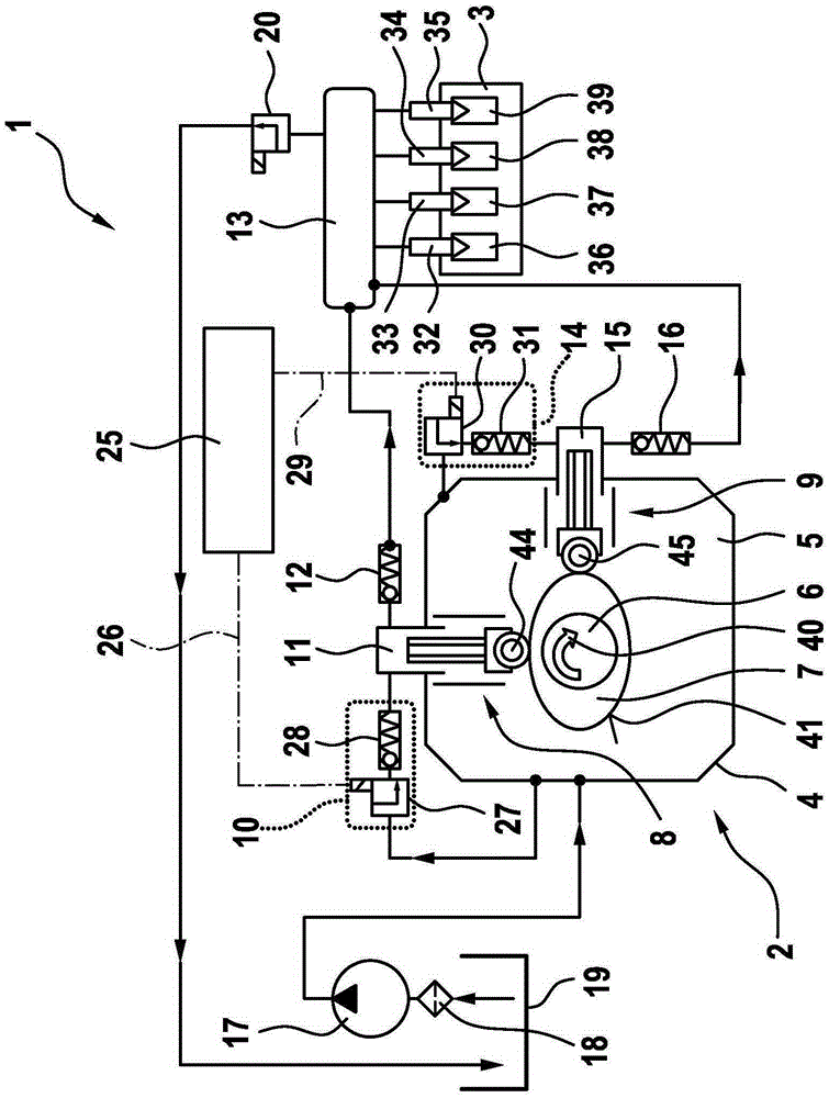
[0019] figure 1 According to an exemplary embodiment, a structural arrangement 1 with a high-pressure pump 2 and an internal combustion engine 3 are shown in a schematic diagram. In particular, the high-pressure pump 2 can be designed as a radial piston pump or as an in-line piston pump. The structural arrangement 1 can be designed in particular as a fuel injection system 1 and be used for a supercharged, self-igniting internal combustion engine 3 .

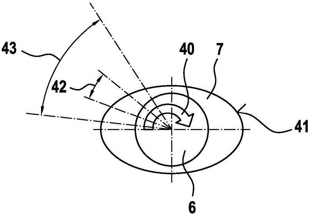
[0020] The high-pressure pump 2 has a pump housing 4 in which a drive mechanism chamber 5 is formed. A drive shaft 6 with a cam 7 is mounted in this pump housing 4 . The cam 7 is designed as a double cam 7 in this exemplary embodiment. In this case, the cam 7 can be configured as a multiple cam according to the corresponding variant. Furthermore, the term “cam” also includes a configuration of the cam 7 in which the drive shaft 6 has an eccentric section or the like.

[0021] The high-pressure pump 2 has a first pump unit 8 ...


PUM


Abstract

A high-pressure pump (2), which is used in particular as a radial or in-line piston pump for fuel injection systems of air-compressing, auto-ignition internal combustion engines (3), comprises a first pump assembly (8), a second pump assembly (9), and a drive shaft (6), which is used to drive the first pump assembly (8) and the second pump assembly (9). Furthermore, a first inlet valve (10) for a pump working chamber (11) of the first pump assembly (8) and at least one second inlet valve (14) for a pump working chamber (15) of the second pump assembly (9) are provided. The first inlet valve (10) is designed as a controlled inlet valve (10), wherein fuel pumping by the first pump assembly (8) can be at least substantially interrupted by the first inlet valve (10) in a partial-load operating mode. The invention further relates to a fuel injection system (1) having such a high-pressure pump (2).

Description

technical field [0001] The invention relates to a high-pressure pump, in particular a radial piston pump or an in-line piston pump, and a fuel injection system having such a high-pressure pump. The invention relates in particular to the field of fuel pumps for fuel injection devices of supercharged self-ignition internal combustion engines. Background technique [0002] A high-pressure pump for a fuel injection system of a supercharged, self-igniting internal combustion engine is known from DE 10 2009 003 054 A1. The known high-pressure pump has at least one pump assembly and a drive shaft, wherein the drive shaft has at least one cam assigned to the pump assembly. The pump assembly has working rollers with rolling surfaces. In this case, the running roller is arranged on the running surface of the cam. The rolling load capacity of the working roller on the running surface of the working roller and the rolling load capacity of the cam on the running surface of the cam are...

Claims


Application Information

Patent Timeline
Patent Type & Authority Applications(China)
IPC IPC(8): F02M59/10F02M59/06F02M59/36F02D41/38F02M63/02F02D41/00F02D41/12
CPCF02M63/027F02D41/0087F02D41/3845F02D41/3854F02M59/06F02M59/102F02M59/366F02M2700/1358F02D41/3082F02D17/02F02D41/30F02M59/02F04B19/22F04B23/06F04B49/22F04B53/10F04B53/16
Inventor M·拉姆
Owner ROBERT BOSCH GMBH
Why Eureka
Try Eureka