U-shaped metal parts processing equipment

A technology for processing equipment and metal parts is applied in the field of U-shaped metal parts processing equipment, which can solve the problems of reducing the processing efficiency of U-shaped metal parts and increasing the processing time of U-shaped metal parts.

Active Publication Date: 2017-04-26
ZHEJIANG RUISHEN AUTO PARTS
View PDF8 Cites 4 Cited by
  • Summary
  • Abstract
  • Description
  • Claims
  • Application Information

AI Technical Summary

Problems solved by technology

The traditional processing method of U-shaped metal parts is to manually bend the straight metal parts with tools in advance, and then put them into the mold for shaping. After the shaping is completed, open the mold and take them out manually. The processing time of U-shaped metal parts is increased, and the processing efficiency of U-shaped metal parts is reduced. However, such small U-shaped metal parts often require a large amount of processing. Improving work efficiency can greatly improve enterprise benefits.

Method used


Image

  • U-shaped metal parts processing equipment
  • U-shaped metal parts processing equipment
  • U-shaped metal parts processing equipment

Examples


Embodiment Construction

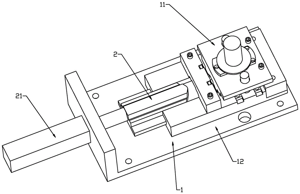
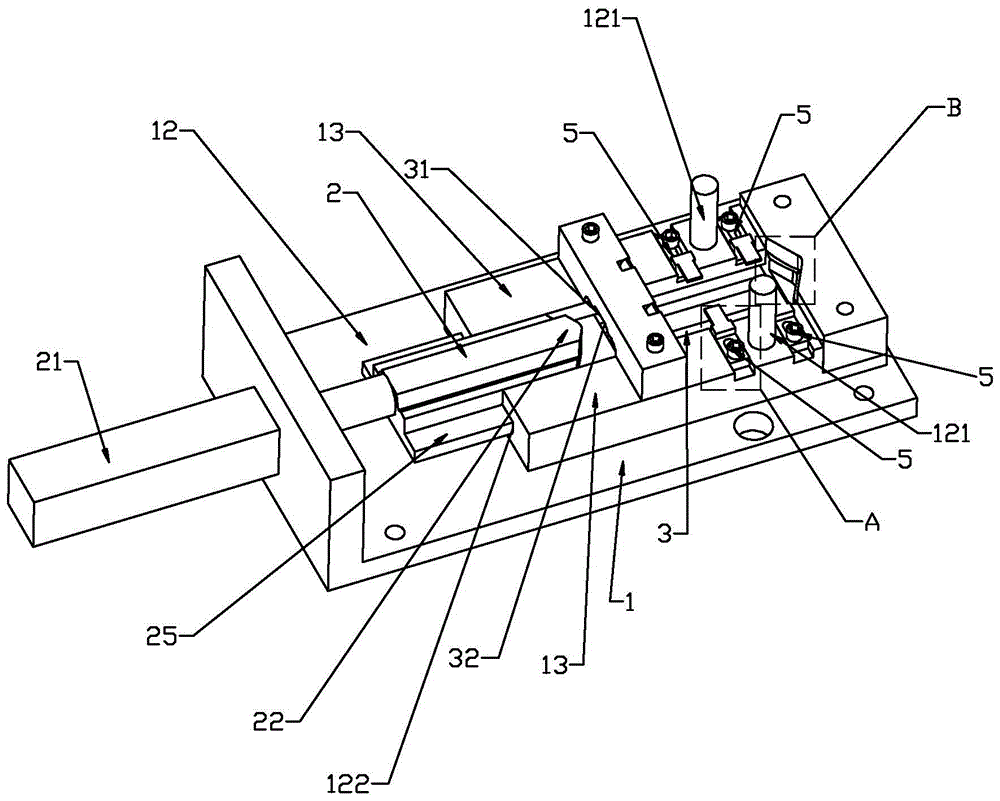
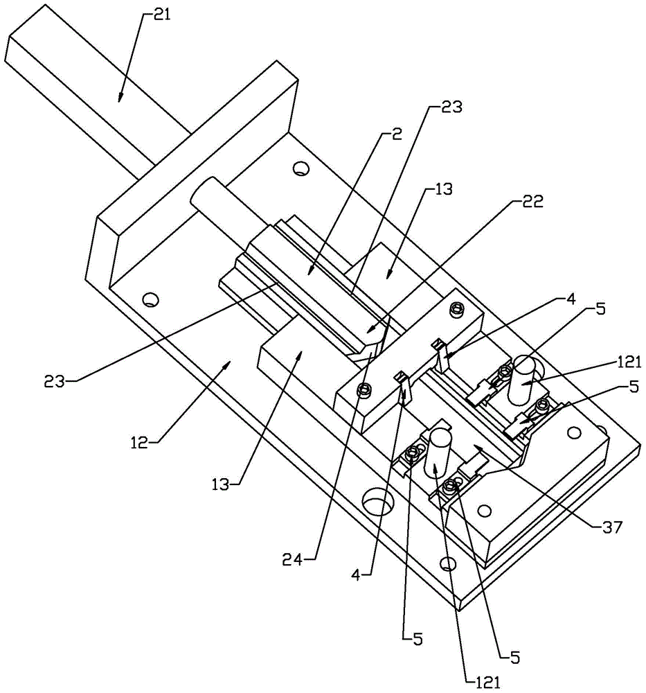
[0025] Such as figure 1 — Figure 8 As shown, the present invention discloses a U-shaped metal piece processing equipment, including a processing seat 1 and a pushing block 2, a processing cavity 3 is arranged in the processing seat 1, and an inlet and outlet 31 is arranged opposite to the pushing block 2 in the processing cavity 3, and the pushing The block 2 is provided with a drive mechanism 21 to push the push block 2 into the processing chamber 3 in a straight line. The end of the push block 2 facing the entrance is used as the push end 22 for pushing the linear metal piece into the processing chamber 3. The processing seat 1 is located in the push block. 2 There are linear metal parts placing platforms 13 on both sides, and the processing chamber 3 is provided with a preliminary processing part, a side shaping part and a bending shaping part along the moving track of the pushing block 2 in sequence, and the preliminary processing part includes moving along the pushing bl...


PUM


Abstract

The invention relates to a machining device for a U-shaped metal part. The machining device comprises a machining seat and a push block. A machining cavity is formed in the machining seat, and an inlet and outlet opening is formed in the position, opposite to the push block, of the machining cavity. The push block is provided with a drive mechanism for linearly pushing the push block into the machining cavity. The end, facing the inlet, of the push block serves as a push end for pushing a linear metal part into the machining cavity, and an initial machining part, a side edge shaping part and a bending shaping part are sequentially arranged in the machining cavity along the moving track of the push block. According to the machining device for the U-shaped metal part with the scheme, one-time molding is achieved, and production efficiency is high.

Description

technical field [0001] The invention relates to a metal piece processing equipment, in particular to a U-shaped metal piece processing equipment. Background technique [0002] U-shaped metal parts, as a common shape of metal parts, are often used in various industries, such as the electrical industry. The traditional processing method of U-shaped metal parts is to manually bend the straight metal parts through tools in advance, and then put them into the mold for shaping. After the shaping is completed, open the mold and take them out manually. This increases the processing time of U-shaped metal parts and reduces the processing efficiency of U-shaped metal parts. However, such small U-shaped metal parts often require a large amount of processing. Improving work efficiency can greatly improve enterprise benefits. Contents of the invention [0003] In view of the deficiencies in the prior art, the purpose of the present invention is to provide a U-shaped metal piece proces...

Claims


Application Information

Patent Timeline
Patent Type & Authority Patents(China)
IPC IPC(8): B21D11/00B21D11/22
CPCB21D11/00B21D11/22
Inventor 贾挺荣赖灿荣贾挺德
Owner ZHEJIANG RUISHEN AUTO PARTS
Why Eureka
Try Eureka