Polishing device

A polishing device and shaft technology, which is applied to surface polishing machine tools, grinding/polishing equipment, grinding machines, etc., can solve the problems of long processing time and complicated processing, and achieve the effect of short processing time and simple structure

Inactive Publication Date: 2015-06-17
SUZHOU RS TECH
View PDF7 Cites 2 Cited by
  • Summary
  • Abstract
  • Description
  • Claims
  • Application Information

AI Technical Summary

Problems solved by technology

[0003] The existing polishing device processes the predetermined shape, the processing is complicated, and the processing time is long

Method used


Image

  • Polishing device
  • Polishing device

Examples


Embodiment Construction

[0022] The present invention will be further described below in conjunction with the accompanying drawings and embodiments.

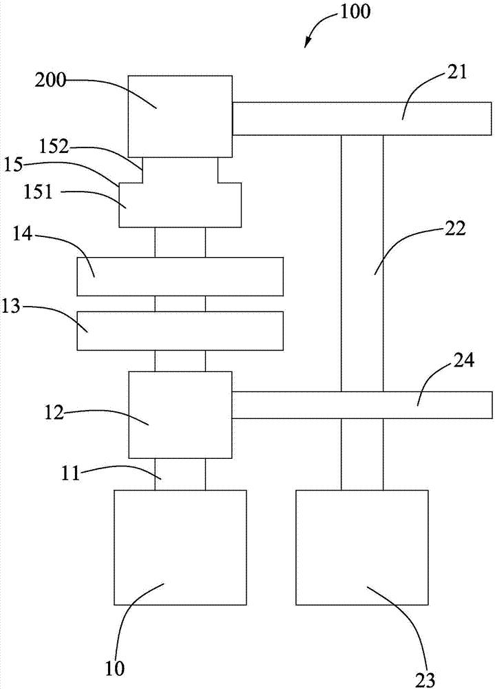
[0023] like figure 1 As shown, it is a polishing device 100 according to the first embodiment of the present invention, which includes a first motor 10, a first rotating shaft 11, a former 12, a first bearing 13, a second bearing 14, a carrier 15, and an abrasive belt Wheel 21, second rotating shaft 22, second motor 23.

[0024] The first rotating shaft 11 and the second rotating shaft 22 are arranged in parallel, and the first motor 10 drives the first rotating shaft 11 to rotate. The second motor 23 drives the second rotating shaft 22 to rotate. The master 12 , the first bearing 13 , the second bearing 14 , and the carrier 15 are all installed on the first rotating shaft 14 and can rotate with the first rotating shaft 11 .

[0025] The first bearing 13 is located in front of the former 12 , the second bearing 14 is located in front of the first bear...


PUM


Abstract

The invention discloses a polishing device which comprises a first motor, a first rotating shaft, a master form, a first bearing, a second bearing, a vehicle, an abrasive belt wheel, a second rotating shaft and a second motor, the first rotating shaft and the second rotating shaft are arranged in parallel, the first motor drives the first rotating shaft to rotate, the second motor drives the second rotating shaft to rotate, the master form, the first bearing, the second bearing and the vehicle are all arranged on the first rotating shaft and can rotate along with the first rotating shaft, the first bearing is located in front of the master form, the second bearing is located in front of the first bearing, and the vehicle is located in front of the second bearing; the polishing device is further provided with a workpiece which is arranged on the first rotating shaft and located at the front end of the vehicle, the abrasive belt wheel is arrange at the front end of the second rotating shaft, and the abrasive belt wheel is used for polishing the workpiece arranged at the front end of the second rotating shaft. The structure of an abrasive belt wheel polishing workpiece is simple, due to the fact that the master form is arranged, the shape of the polishing workpiece conforms to the shape of the master form, and the machining time is short.

Description

technical field [0001] The invention relates to a polishing device, in particular to a polishing device with a simple structure. Background technique [0002] The polishing machine is a kind of electric tool. The polishing machine is composed of basic components such as a base, a throwing plate, a polishing fabric, a polishing cover and a cover. The motor is fixed on the base, and the taper sleeve used for fixing the polishing disc is connected with the motor shaft through screws. The polishing fabric is fastened on the polishing disc through a ferrule. After the motor is powered on through the switch on the base, the sample can be polished by hand to apply pressure on the rotating polishing disc. The polishing fluid added during the polishing process can flow into the square plate next to the polishing machine through the drain pipe in the plastic plate fixed on the base. The polishing cover and cover can prevent dust and other debris from falling on the polishing fabric ...

Claims


Application Information

Patent Timeline
Patent Type & Authority Applications(China)
IPC IPC(8): B24B17/02B24B21/00
CPCB24B17/02B24B29/00
Inventor 吴加富缪磊
Owner SUZHOU RS TECH
Why Eureka
Try Eureka