A Method for Digitized Angle Determination of Pipeline

A fixed angle and pipeline technology, applied in applications, household appliances, tubular objects, etc., can solve the problems of unguaranteed reproducibility and consistency, poor processing stability and consistency, repeated samples, etc., to avoid turnover and repetition work, shorten the production cycle, and facilitate batch production and processing

Active Publication Date: 2017-03-22
AECC AVIATION POWER CO LTD
View PDF5 Cites 0 Cited by
  • Summary
  • Abstract
  • Description
  • Claims
  • Application Information

AI Technical Summary

Problems solved by technology

[0006] (2) Long cycle: due to its harsh processing conditions, the processing of conduit parts must be carried out after the complete machine has been basically assembled. Therefore, nearly 1 / 2 of the estimated processing cycle of conduit parts wasted waiting
There is too much waiting and repetition in the whole processing process, and the cycle is long
[0007] (3) Poor processing stability and consistency: Due to the limitation of processing conditions, the quality of sampling mainly depends on the following two points: ①The quality of the whole machine assembly used for sampling; ②The operation skills of the fitter who operates the sampling
If any point goes wrong, it will lead to repeated calibration and repair of the sample
Furthermore, since the entire sampling process is manual, there is no corresponding data support, the randomness is too large, and the reproducibility and consistency cannot be guaranteed. The above problems are hidden dangers for the later use of catheter parts.
[0008] With the rapid development of UG modeling technology in the field of aviation manufacturing and the gradual improvement of the processing capabilities of production equipment, only with the help of UG design drawings of conduit parts, the tube shape direction of conduit parts can be determined, and a single tube can be easily processed. Pipe fittings, but the determination of the angular direction of the matching joints on it can rely on on-site trial assembly and sampling, or use the corresponding assembly fixture to determine, so that the shortcomings in the entire processing process have not been improved due to the easy determination of the direction of the pipe type

Method used


Image

  • A Method for Digitized Angle Determination of Pipeline
  • A Method for Digitized Angle Determination of Pipeline
  • A Method for Digitized Angle Determination of Pipeline

Examples


Embodiment Construction

[0039] The present invention will be described in detail below in conjunction with the accompanying drawings.

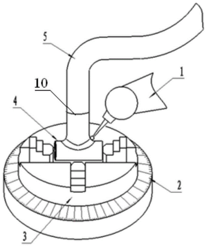
[0040] Assume that the conduit with the spatial angular joint is properly assembled and that the joint at the end of the pipe is a curved segment of the conduit.

[0041] 1) Use UG software to obtain auxiliary model space data:

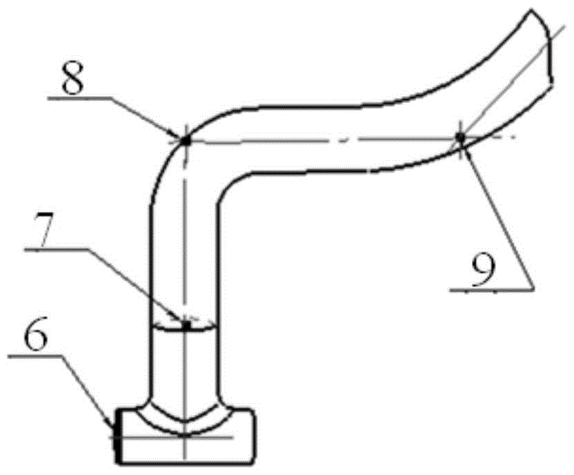
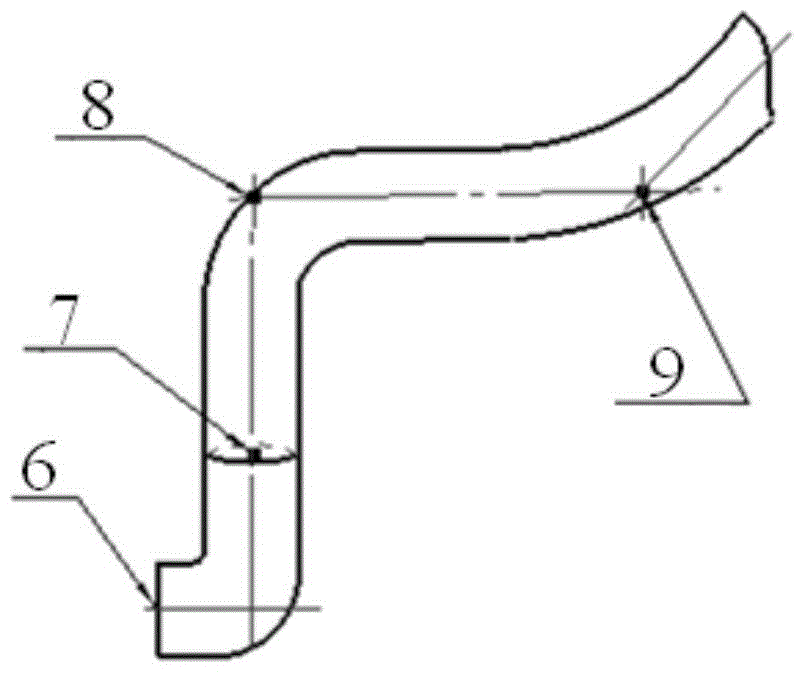
[0042] see figure 2 with image 3 , the intersection coordinates of the centerlines of each section of the pipe assembly to be processed can be captured from the UG design drawing, including the intersection coordinates at the corner of the joint and the coordinates of the center point of the joint end face. The coordinates of the intersection point 8 of the two axes of the pipe and the intersection point 9 of the two axes of the second pipe.

[0043] The principle of capturing point coordinates: Since two intersecting straight lines can determine a plane, and the purpose of capturing points this time is to determine the spatial angular ...


PUM


Abstract

The invention discloses a method for digitally determining an angular direction of a pipeline. The method comprises the steps that a connector is clamped on a clamp with the indexing function; a matched guide tube is assembled on the connector according to any space angle; a tubular measurer is used for carrying out point collecting on the outer surface of the matched guide tube and the outer surface of the connector, a space data model is obtained through measurement of the tubular measurer, and the space data model is a model with the connector end assumed as the guide tube; data intercepted from UG modeling is used as standard data, data measured from the connector and the matched guide tube is used as correlation data, and therefore simulated data deviation is obtained; then angular deviation is calculated; measurement and adjustment are performed again after the angle is adjusted, and the assembling angle direction is marked on the connector and the matched guide tube till the measurement tolerance is within the allowed assembling tolerance range of the connector. The method can directly determine the angular direction of the connector of a part like the guide tube through UG modeling graphs, and is applicable to parts like guide tubes of any tube diameter, so that the parts are machined more easily, conveniently and efficiently with low cost.

Description

technical field [0001] The invention relates to the technical field of manufacturing catheter parts, in particular to a method for digitally determining the angle of pipelines. Background technique [0002] There are a large number of duct parts on the aero-engine, and there are many part numbers involved, but most of the same part number only uses one piece. Therefore, the processing characteristics of the same type of duct parts are "multiple specifications and small batches". Due to their functional characteristics, different part numbers have complex shapes and structures, different thicknesses, and different lengths. There are no two parts with the same tube shape on the same engine. Due to the corresponding assembly relationship of each tube, its tube There are differences in the direction of the pipe type and the angular direction of the joint space. Therefore, for a long time, only the matching relationship has been specified in the design drawings of the engine duct...

Claims


Application Information

Patent Timeline
Patent Type & Authority Patents(China)
IPC IPC(8): B23K37/053
CPCB23K37/053B23K2101/06
Inventor 张强虎冯锦丽王璟冯璐刘红旗江洪飞班锦强包钰锋
Owner AECC AVIATION POWER CO LTD
Why Eureka
Try Eureka