Integrated automatic production equipment based on stem guide wire shaping and LED light bar welding

A technology of LED light strips and production equipment, which is applied to other manufacturing equipment/tools, manufacturing tools, etc., and can solve problems that affect production efficiency and production quality, low precision, and more production

Active Publication Date: 2018-08-28
南通睿博电器有限公司
View PDF8 Cites 0 Cited by
  • Summary
  • Abstract
  • Description
  • Claims
  • Application Information

AI Technical Summary

Problems solved by technology

[0002] When welding the LED light bar, it is generally necessary to bend the four short metal feet at the front end of the stem guide wire and the long metal foot at the rear end first, and then weld the LED light bar with the guide wire through the welding mechanism to form a whole. In the end, it is welded between a long metal leg and a short metal leg. Because the guide wire of the stem is thinner and softer, in order to save costs, it is mainly necessary to first position the guide wire of the stem and move the long leg. Opening, short leg opening, long leg dialing 45 degrees, short leg dialing 45 degrees, horizontal straight leg, vertical straight leg, light bar cutting and feeding, and welding steps, etc., these existing steps are all done manually, The accuracy and efficiency of manual operation are low, and more defective products will be produced, which will affect the production efficiency and production quality. At present, there is no automatic automatic equipment for the automatic shaping and welding of the stem guide wire.

Method used


Image

  • Integrated automatic production equipment based on stem guide wire shaping and LED light bar welding
  • Integrated automatic production equipment based on stem guide wire shaping and LED light bar welding
  • Integrated automatic production equipment based on stem guide wire shaping and LED light bar welding

Examples


Embodiment

[0176] Gap divider 8, the input shaft continuously rotates one week and the output shaft can be used as a mechanism for stopping and rotating. The desired action can be completed during the stop period.

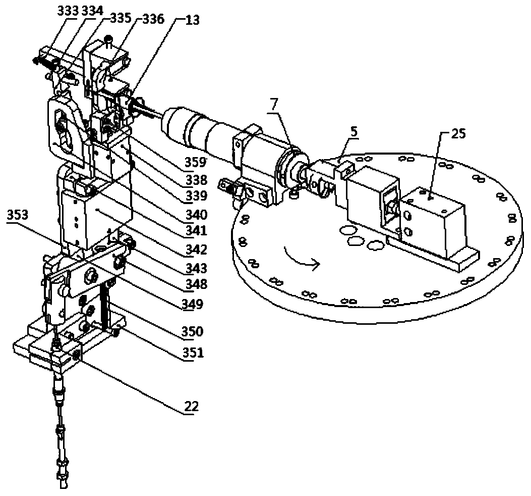
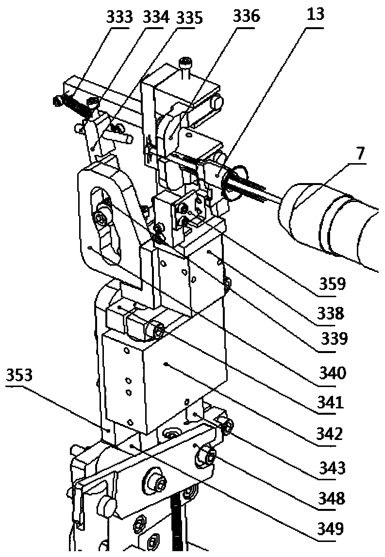
[0177] The indexing disc 5 has been reduced for the convenience of display, and the indexing disc 5 is fixed on the output shaft end of the divider, the gap divider 8, the long-legged 45-degree assembly mechanism (in the rectangular frame A) and the stem left and right The positioning mechanisms (in the rectangular frame B) are all fixed on a platen 3 .

[0178] The bottom slide rail seat 718 for straightening the long feet is rotated by the motor through the belt, the reducer 10, the station main shaft, and the gears, and the jaw cylinder is pushed upward by the lever 12 and the connecting rod. When the upward push is in place, the jaw cylinder moves , the horn front end plane of the stem 13 is clamped by the positioning chuck 703 connected with the clamping jaws, so that t...

Embodiment 2

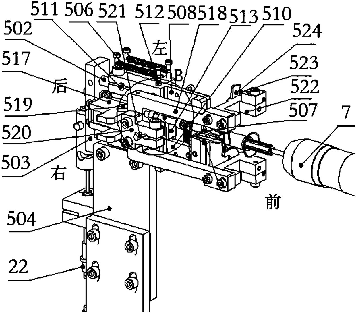
[0191] Such as figure 1 As shown, the short leg of the LED light bar automatically dials the 45-degree device, which is used to dial the four short metal legs connected to the stem 13 to make about 90 degrees to each other, including the connection on the indexing disc 5 in sequence. The stem clamp 7, the gap divider 8, the stem positioning device, and the toggle device; the stem positioning device and the toggle device are respectively connected to the same transmission shaft through a positioning and transmission cam to rotate cooperatively, wherein: the stem Positioning device: including a positioning chuck 802 concentric with the core column clamp 7, a cylinder seat for shifting feet, a guide rail seat, an air cylinder for shifting feet, a positioning guide post, a positioning slider 805, a guide rail seat cam 806, and a rocker arm 808 for shifting feet, Thick pull rope 22, the cylinder for shifting feet is connected in the cylinder seat for shifting feet to drive the posi...


PUM


Abstract

The invention discloses full-automatic production equipment based on stem guide wire shaping and LED light strip welding integration. The full-automatic production equipment comprises a main bottom plate, a platen and an upper bracket, wherein the upper end of the main bottom plate supports the platen through four thick bracket legs. A discharging mechanism and a buffering conveying mechanism are arranged on the left and the right of the side surface of the platen respectively, and a feed mechanism is arranged at the end of the buffering conveying mechanism. The platen is provided with a gap divider. An index plate rotates anticlockwise and is provided with a stem clamp. The main bottom plate is provided with a speed reducer, a station main shaft and a cam mechanism. A stem locating mechanism, a long foot arranging mechanism, a short foot poking mechanism, a 45-degree long foot poking assembly mechanism, a 45-degree short foot poking assembly mechanism, a foot straightening mechanism, an LED light strip shearing and conveying mechanism, an automatic LED light strip rotating and conveying mechanism and a welding mechanism are sequentially arranged on the platen from the front end of the feed mechanism and surround the index plate. The full-automatic production equipment is high in automation degree, high in welding and shaping efficiency and high in shaping accuracy.

Description

technical field [0001] The invention relates to the technical field of LED light bar processing and manufacturing, in particular to a fully automatic production equipment based on the integration of stem guide wire shaping and LED light bar welding. Background technique [0002] When welding the LED light bar, it is generally necessary to bend the four short metal feet at the front end of the stem guide wire and the long metal foot at the rear end first, and then weld the LED light bar with the guide wire through the welding mechanism to form a whole. In the end, it is welded between a long metal leg and a short metal leg. Because the guide wire of the stem is thinner and softer, in order to save costs, it is mainly necessary to first position the guide wire of the stem and move the long leg. Opening, short leg opening, long leg dialing 45 degrees, short leg dialing 45 degrees, horizontal straight leg, vertical straight leg, light bar cutting and feeding, and welding steps, ...

Claims


Application Information

Patent Timeline
Patent Type & Authority Patents(China)
IPC IPC(8): B23P23/00
CPCB23P23/00
Inventor 张小强汤国忠
Owner 南通睿博电器有限公司
Why Eureka
Try Eureka