Combined circuit board chemical treatment line equipment and treatment method thereof

A technology of chemical treatment and treatment method, which is applied in the field of combined circuit board chemical treatment line equipment and its treatment, which can solve the problems of unfavorable integration and utilization of the same process, large footprint of single line body, product oxidation, etc., and achieve convenient automatic treatment operation Effect

Pending Publication Date: 2020-03-24
东莞市鸿展机电设备有限公司
View PDF0 Cites 0 Cited by
  • Summary
  • Abstract
  • Description
  • Claims
  • Application Information

AI Technical Summary

Problems solved by technology

Electroless copper plating, chemistry is each kind of electroplating or surface; the existing technology has the following defects: 1. The single wire body occupies a large area, and each electroplating line is about 14 meters long and 5 meters wide, which is not conducive to space Utilization; 2. Different electroplating or surface treatment processes are processed separately, which is not conducive to the integration and utilization of the same process;

Method used


Image

  • Combined circuit board chemical treatment line equipment and treatment method thereof
  • Combined circuit board chemical treatment line equipment and treatment method thereof
  • Combined circuit board chemical treatment line equipment and treatment method thereof

Examples


Embodiment 1

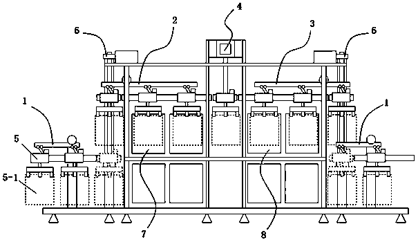
[0040] Example 1, please refer to Figure 1~4 A combined circuit board chemical processing line equipment, including a frame, the frame is provided with a left-right symmetrical front processing groove 7 and a rear processing groove 8, between the front processing groove 7 and the rear processing groove 8 A transfer mechanism 4 is provided, and the frame is provided with a front processing transport mechanism 2 corresponding to the front section processing tank 7, and the frame is provided with a plate entry transport mechanism 1 corresponding to the front processing transport mechanism 2, and the plate entry transport mechanism 1 is arranged at the bottom of the frame. A plate lifting mechanism is set between the plate-in transport mechanism 1 and the front-processing transport mechanism 2, and the post-processing transport mechanism 3 is provided on the frame corresponding to the rear processing tank 8, and the plate-out transport mechanism is provided on the frame correspond...

Embodiment 2

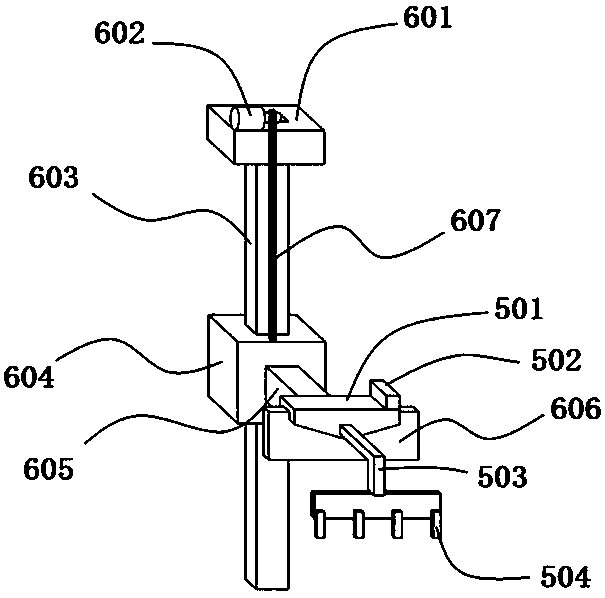
[0046] Embodiment two, refer to Figure 5 , the present embodiment adds the following technical features on the basis of Embodiment 1: the lifting fixture mechanism 6 also includes vertical support beams 608 symmetrically arranged left and right on the frame, the top platform 601 is arranged on the top of the two vertical support beams 608, and the two A horizontal support beam 609 is arranged between the bottoms of the vertical support beams 608. There are two sliding rods 603 arranged symmetrically along the horizontal support beams 609. Set in the middle of the top platform 601, the suspension motor 602 is a double-head motor, and the two ends are connected with the sliding sleeve 604 through the suspension chain 607.

Embodiment 3

[0047] Embodiment three, refer to Image 6 , the difference between this embodiment and Embodiment 1 is:

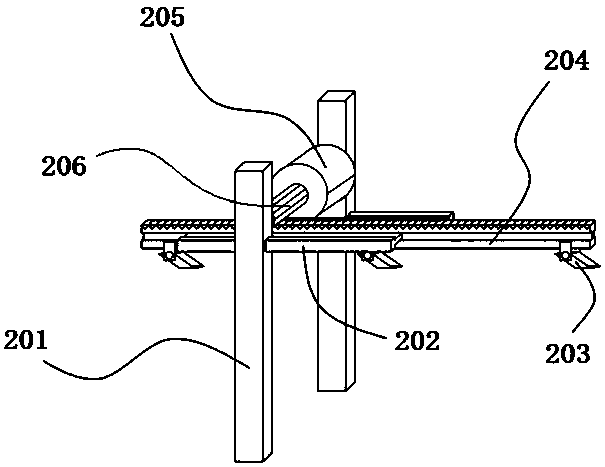
[0048] Wherein, the transfer moving mechanism is a belt vehicle-mounted mobile mechanism, including a vehicle-mounted beam 412 arranged on the frame, and fixed frames 411 are symmetrically arranged at both ends of the vehicle-mounted beam 412, and the vehicle-mounted beam 412 is suspended and installed on the frame through the fixed frame 411 , the two ends of the vehicle-mounted beam 412 are fitted with a belt shaft 414, the belt shaft 414 is equipped with a transmission belt 410, the vehicle-mounted beam 412 is slidably fixed with a vehicle-mounted seat 413, the vehicle-mounted seat 413 is fixedly connected with the transmission belt 410, and the top of the connecting rod 404 It is fixed on the lower side of the vehicle seat 413, and the belt shaft 414 on one side is connected with a relay stepping motor 401.

[0049] see Figure 7-8 , Embodiment 1 to Embodiment 3: a ...


PUM


Abstract

The invention discloses combined type circuit board chemical treatment line equipment. The equipment comprises a machine frame. A front section machining groove and a rear section machining groove areformed in the rack in a bilateral symmetry mode. A transfer mechanism is arranged between the front-section machining groove and the rear-section machining groove. The rack is provided with a front processing and conveying mechanism corresponding to the front-section processing groove. The invention provides combined type circuit board chemical treatment line equipment. The equipment has a front-section machining groove and a rear-section machining groove, and a transfer mechanism is arranged between the front-section machining groove and the rear-section machining groove. The machining sections of the line bodies are sequentially arranged through the transfer mechanism, and then the line bodies are arranged in parallel, the middles of the line bodies are connected through the transfer mechanism, and the head ends and the tail ends of the line bodies are connected with the transfer mechanism. The equipment performs common post-processing, unloads plates, folds plates, and performs post-processing of clamps. An independent line body is arranged and connected with a machining line body through a transfer mechanism, line body sharing of the same technological process is achieved, andmachining processes and devices with different machining effects are distributed through the transfer mechanism.

Description

technical field [0001] The invention belongs to the technical field of circuit board processing, in particular to a combined circuit board chemical processing line equipment and a processing method thereof. Background technique [0002] There are many types of circuit board electroplating, including electroplating copper, electronickel, electrotin, electroplating gold, etc., and there are many types of circuit board surface treatment, including chemical immersion gold, chemical immersion tin, chemical immersion nickel, immersion silver and so on. At present, the electroplating or surface treatment line used for circuit board production is generally set to a single line body mode, and the surface treatment process requires an independent line body for processing. Electroless copper plating, chemistry is each kind of electroplating or surface; the existing technology has the following defects: 1. The single wire body occupies a large area, and each electroplating line is about...

Claims


Application Information

Patent Timeline
IPC IPC(8): H05K3/18
CPCH05K3/18H05K2203/0195H05K2203/0723
Inventor 刘长春李星移
Owner 东莞市鸿展机电设备有限公司
Why Eureka
Try Eureka