Method for manufacturing wind power blade crossbeam mold

A wind power blade and blade technology, which is applied in the field of wind power blade girder mold production, can solve problems affecting blade service life, web top mold, girder structure damage, etc. Effect

Active Publication Date: 2016-02-24
LUOYANG SUNRUI WIND TURBINE BLADE
View PDF4 Cites 14 Cited by
  • Summary
  • Abstract
  • Description
  • Claims
  • Application Information

AI Technical Summary

Problems solved by technology

During the forming process of the girder, there will be different degrees of deviation in the starting and ending positions of each layer of uniaxial cloth after it is placed, so that the thickness of the girder at this position will change, and after the girder is poured into the blade shell, it will make The mold clamping gap of the blade at this position changes, and the smaller the mold clamping gap will cause the top mold of the web, the larger the mold clamping gap will cause defects such as virtual sticking between the web and the shell
In addition, when the girder is produced in the female mold, if the girder has defects such as air leakage or unsaturated dry yarn, these defects will be concentrated on the upper surface of the girder, and each layer of uniaxial cloth of the girder formed in the female mold has a part exposed on the upper surface of the girder, which results in this defect often occurring in many layers of the girder
Therefore, when repairing these defects, many layers of the girder will be damaged, which not only increases the difficulty of maintenance, but even if the effect of maintenance is not considered, the structure of the girder itself has been damaged, so that the mechanical properties and fatigue resistance of the girder Decreased performance, affecting blade service life

Method used


Image

  • Method for manufacturing wind power blade crossbeam mold
  • Method for manufacturing wind power blade crossbeam mold
  • Method for manufacturing wind power blade crossbeam mold

Examples


Embodiment Construction

[0040] The present invention is described in conjunction with accompanying drawing and specific embodiment, and this embodiment takes the making of the male mold mold of the lee side girder of the 55.2 meter blade of lengthening type 2MW as an example;

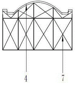
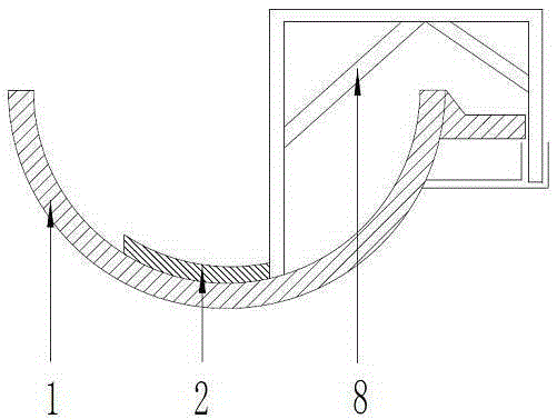
[0041] Such as figure 1 , figure 2 As shown, a method for manufacturing a wind power blade girder mold, the basic steps of making a wind power blade girder mold are to make a blade male mold, and turn the blade female mold 1 on the blade male mold; after the blade female mold 1 is manufactured , make a standard blade girder model 2 on the blade female mold 1, and then turn the blade girder male mold on the blade girder model 2; the specific manufacturing steps are:

[0042] 1) Preparation of the male blade mold: According to the cross-sectional shape of each position in the electronic model of the blade, the iron profile plate of each position of the blade is obtained by laser cutting method, and the iron profile plate is as...


PUM


Abstract

The invention belongs to the technical field of wind power generation and particularly relates to a method for manufacturing a wind power blade crossbeam mold. The method for manufacturing the wind power blade crossbeam mold comprises the steps that a blade male mold body is manufactured, and a blade female mold body is remanufactured on the blade male mold body; and after the blade female mold body is manufactured, a standard blade crossbeam model is manufactured on the blade female mold body, and then a blade crossbeam male mold body is remanufactured on the blade crossbeam model. According to the method for manufacturing the wind power blade crossbeam mold, a gap between a blade shell and an anti-shear web can be accurately controlled or adjusted; when the crossbeam male mold body is used for producing a crossbeam, it seems that all layers of the crossbeam become longer gradually one by one through a unique step-shaped structure of the crossbeam male mold body, namely each layer can be covered with the layer above; the probability that the mechanical property is reduced due to the fact that the structure of the crossbeam is damaged can be avoided or lowered to the maximum extent.

Description

technical field [0001] The invention belongs to the technical field of wind power generation, and in particular relates to a manufacturing method of a wind power blade girder mold. Background technique [0002] With the development of new energy development, more and more attention has been paid to wind power generation, which has ushered in a high-speed development opportunity in recent years. With the steady increase in the total number of installed wind turbines, wind turbine blades have also developed rapidly. [0003] Wind power blades are composed of multiple parts, such as girders, webs, sandwich layers, lightning protection systems and root connection systems, etc. Among them, the girder is the most important structural part of the entire blade. It is the area with the most concentrated stress during the operation of the blade. It needs to bear the bending moment generated by the deformation of the blade, and is the main component of the blade's anti-fatigue. Due t...

Claims


Application Information

Patent Timeline
Patent Type & Authority Applications(China)
IPC IPC(8): B29C70/34B29C33/38
CPCB29C33/3842B29C70/342
Inventor 李重阳杜瑞林明
Owner LUOYANG SUNRUI WIND TURBINE BLADE
Why Eureka
Try Eureka