Spraying type jig dyeing machine

A jigger and spray technology, applied in the field of dyeing and finishing machinery, can solve the problems of damage to the surface of the fabric, uneven dyeing, and difficult cleaning of impurities, and achieve the effects of reducing damage, good dyeing effect, and uniform spraying.

Active Publication Date: 2016-02-24
ANHUI YAYUAN PRINTING & DYEING CO LTD
View PDF7 Cites 6 Cited by
  • Summary
  • Abstract
  • Description
  • Claims
  • Application Information

AI Technical Summary

Problems solved by technology

[0005] However, in the prior art, whether it is dip dyeing or spray dyeing, it is necessary to support the cloth to be dyed during the transmission process through the middle support roller, and the friction of the support rolle

Method used


Image

  • Spraying type jig dyeing machine
  • Spraying type jig dyeing machine
  • Spraying type jig dyeing machine

Examples


Embodiment Construction

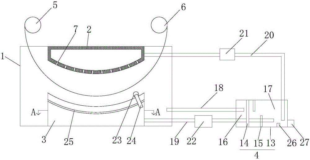
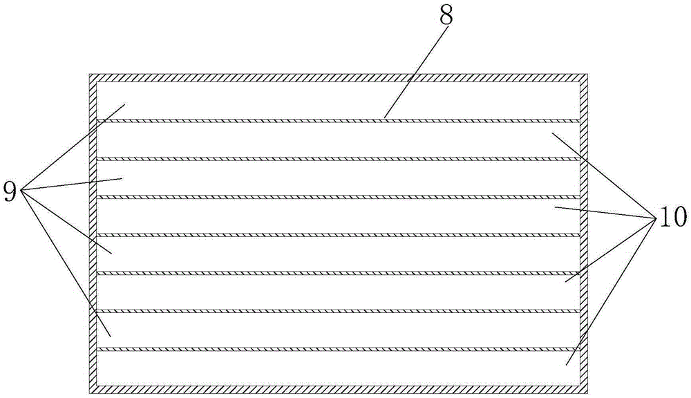
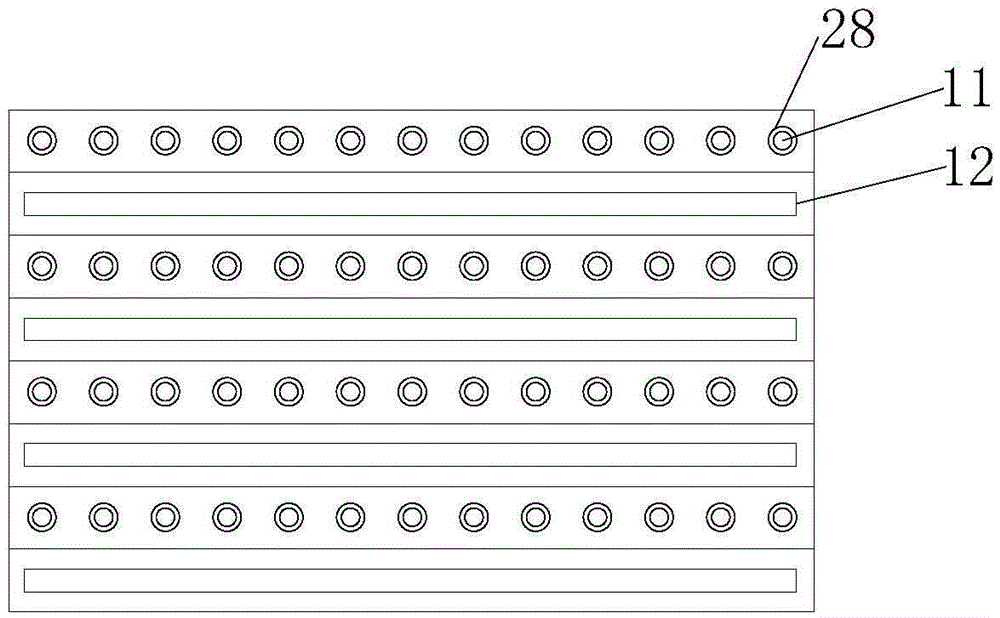
[0025] Such as figure 1 , figure 2 and image 3 as shown, figure 1 It is a structural schematic diagram of a spray jigger proposed by the present invention; figure 2 It is the A-A sectional schematic diagram of the lower spray recovery box in a spray jigger proposed by the present invention; image 3 It is a top view structure diagram of the middle and lower spray recovery box of a spray-type dyeing jigger proposed by the present invention.

[0026] refer to Figure 1-3 , a kind of spray jigger proposed by the present invention comprises a printing and dyeing box 1, an upper spray box 2, a lower spray recovery box 3 and a heating filter box 4;

[0027] The upper spray box 2 and the lower spray recovery box 3 are both arranged in the printing and dyeing box 1, the upper spray box 2 is located directly above the lower spray recovery box 3, the bottom wall of the upper spray box 2 is in a convex arc shape, and the lower The top wall of the spray recovery box 3 is in a con...


PUM


Abstract

The invention discloses a spraying type jig dyeing machine which comprises a printing and dyeing box, an upper spraying box, a lower spraying and recycling box and a heating filtering box. The bottom wall of the upper spraying box is in a downward protruding arc shape. The top wall of the lower spraying and recycling box is in a downward concave arc shape. An arc-shaped distribution channel is formed between the bottom wall of the upper spraying box and the top wall of the lower spraying and recycling box. The bottom wall of the upper spraying box is provided with multiple upper spraying holes. The section of the top wall of the lower spraying and recycling box in the normal plane is in sine or cosine shape. Partition boards divide the inner cavity of the lower spraying and recycling box into spraying cavities and recycling cavities. The spraying cavities are opposite to the peak position. The peak position is provided with multiple lower spraying holes. The recycling cavities are opposite to the trough position provided with a recycling groove. The spraying cavities are sequentially communicated, and the recycling cavities are communicated with the printing and dyeing box. The heating filtering box comprises a heat-preserving box body, a filtering screen and a heating bar. The heating bar is arranged in a second cavity and close to the filtering screen. A first cavity is communicated with the printing and dyeing box through a first pipe. The printing and dyeing effect is good, printing and dyeing are uniform, and dye is saved.

Description

technical field [0001] The invention relates to the technical field of dyeing and finishing machinery, in particular to a spray-type dyeing jigger. Background technique [0002] Cloth is widely used in our life. It can be used not only to make clothes, but also as a decorative material. No matter which field it is used in, the dyeing of cloth plays a very important role. [0003] In the existing cloth dyeing devices, the method of dip dyeing is mostly used for dyeing cloth, which wastes dyeing liquor. At the same time, it is difficult to clean the dirt left by the cloth in the dyeing liquor during the dyeing process, which affects the dyeing effect. [0004] Dyeing is carried out by spraying, which saves more dyes. [0005] However, in the prior art, whether it is dip dyeing or spray dyeing, it is necessary to support the cloth to be dyed during the transmission process through the middle support roller, and the friction of the support roller to the cloth has the risk of da...

Claims


Application Information

Patent Timeline
IPC IPC(8): D06B3/32D06B23/20
Inventor 潘学东
Owner ANHUI YAYUAN PRINTING & DYEING CO LTD
Why Eureka
Try Eureka