Longitudinal pushing structure of closure segment of continuous rigid frame bridge

A technology for closing sections and rigid frame bridges, which is applied in the field of longitudinal jacking structures for closing sections of continuous rigid frame bridges, which can solve the problems of long time consumption, small space for jacking operations, and increased costs, and achieve simplification and reduction of installation and dismantling work. The effect of improving operation difficulty and pushing efficiency

Inactive Publication Date: 2016-02-24
CCCC TUNNEL ENG
View PDF4 Cites 4 Cited by
  • Summary
  • Abstract
  • Description
  • Claims
  • Application Information

AI Technical Summary

Problems solved by technology

To sum up, in the existing technology, an additional jacking device is added to increase the cost. The jacking operation space is small, the difficulty is high, and the jacking efficiency is low. Due to the cumbersome installation and removal of the jacking system, the jacking takes a long time

Method used


Image

  • Longitudinal pushing structure of closure segment of continuous rigid frame bridge
  • Longitudinal pushing structure of closure segment of continuous rigid frame bridge
  • Longitudinal pushing structure of closure segment of continuous rigid frame bridge

Examples


Embodiment Construction

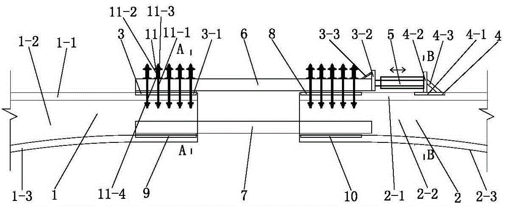
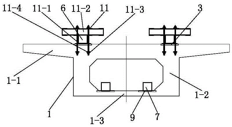
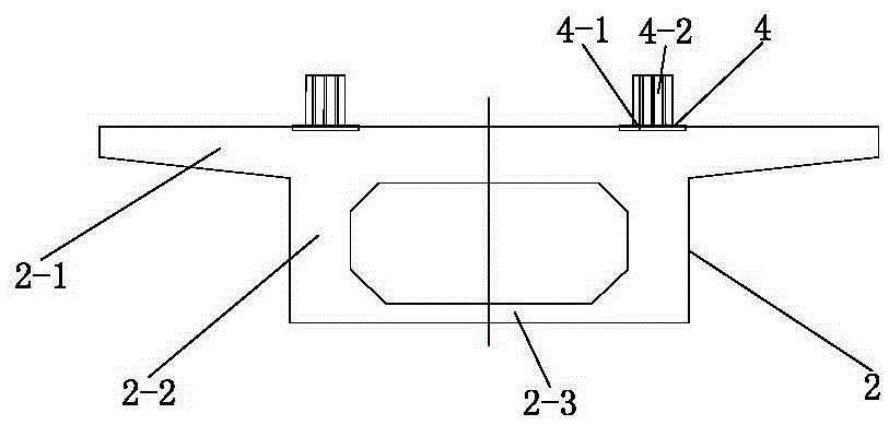
[0061] like Figure 1 to Figure 3 As shown, the longitudinal push structure of a continuous rigid frame bridge closing section provided by this embodiment includes a left main girder 1 and a right main girder 2, the left main girder 1 is fixed with a left push supporting part 3, and the right main girder The main beam 2 is fixed with a right push support part 4, and the left push support part 3 and the right push support part 4 are pushed and connected by a push part 5, and the left push support part 3 is connected with the right push support part 4. The top surface of the left main beam 1 is fixedly connected, and the right push support member 4 is fixedly connected with the top surface of the right main beam 2 . As a preference, from figure 1 It can be seen from the figure that the pushing part 5 is a jack, and the jack is a hydraulic jack, a screw jack, or a scissor jack.

[0062] In this embodiment, since the left push support part is fixedly connected to the top surface...


PUM


Abstract

The invention discloses a longitudinal pushing structure of a closure segment of a continuous rigid frame bridge. The longitudinal pushing structure comprises a left main girder and a right main girder, wherein left pushing support components are fixed on the left main girder, right pushing support components are fixed on the right main girder, the left pushing support components and the right pushing support components are connected in a pushing manner through pushing components, the left pushing support components are fixedly connected with the top surface of the left main girder, and the right pushing support components are fixedly connected with the top surface of the right main girder. According to the longitudinal pushing structure disclosed by the invention, steel plates do not need to be pre-buried in the end surface of the left main girder and the end surface of the right main girder to be used for welding the pushing support components, and main reinforcements do not need to be cut off at the places where the steel plates are supposed to be pre-buried in the top surface of the left main girder and the top surface of the right main girder, so that the connection of prestressed bellows is not influenced, the operating space can be greatly enlarged, the operating difficulty is greatly reduced, the pushing efficiency is greatly improved, the mounting work and the disassembling work of the pushing support components are greatly simplified and are convenient, and the time consumed in the pushing process is short.

Description

technical field [0001] The invention relates to a building structure, in particular to a longitudinal pushing structure of a continuous rigid frame bridge closing section. Background technique [0002] Long-span high-pier prestressed concrete continuous rigid-frame bridge is the most competitive bridge type across deep ditches, rivers, lakes and seas. Due to the impact of concrete shrinkage and creep, the main pier of this type of bridge is deviated greatly after the completion of the bridge, which makes the stress on the bottom of the pier and the pier-beam consolidation extremely unfavorable. At the same time, due to the temperature drop, tensile stress is generated inside the bridge. In order to eliminate the above-mentioned unfavorable factors, the jacking force is generally carried out when the middle span of the rigid frame bridge is closed, that is, the jacking force is applied between the end faces of the left main girder and the end face of the right main girder, so...

Claims


Application Information

Patent Timeline
Patent Type & Authority Applications(China)
IPC IPC(8): E01D21/10
CPCE01D21/10
Inventor 黄玉江刘金山
Owner CCCC TUNNEL ENG
Why Eureka
Try Eureka