Industrial flue gas waste heat recovery device based on liquid metals

A waste heat recovery device and liquid metal technology, applied in the chemical industry, climate sustainability, sustainable manufacturing/processing, etc., can solve the problems of increasing the processing pressure of downstream equipment, increasing the flow rate of acetylene flue gas, and increasing costs. Achieve the effects of reducing the processing pressure, fully exchanging heat, and enhancing the effect of heat exchanging

Active Publication Date: 2016-02-24
BEIJING EMIKON TECH DEV
View PDF8 Cites 4 Cited by
  • Summary
  • Abstract
  • Description
  • Claims
  • Application Information

AI Technical Summary

Problems solved by technology

However, the following problems will arise: (1) A large amount of quenched water injected into water vapor will cause the composition of acetylene flue gas to change, and the flow rate of acetylene flue gas will suddenly increase, which will not only affect the quality of acetylene , and increased the processing pressure of the downstream equipment, the corrosion of the equipment is also more

Method used


Image

  • Industrial flue gas waste heat recovery device based on liquid metals
  • Industrial flue gas waste heat recovery device based on liquid metals
  • Industrial flue gas waste heat recovery device based on liquid metals

Examples


Embodiment 1

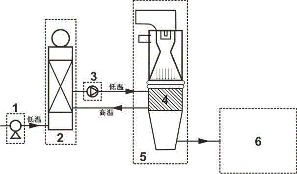
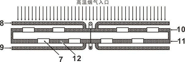
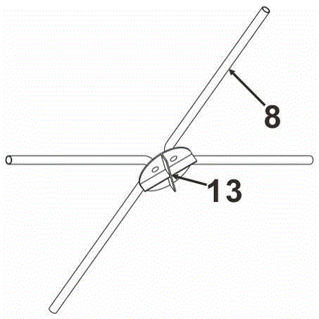
[0041] Example 1 shows a typical application of the liquid metal-based industrial flue gas waste heat recovery device of the present invention. figure 1 It is a structural schematic diagram of an industrial flue gas waste heat recovery device based on liquid metal. figure 2 It is a schematic diagram of the structure of the basic heat exchange unit of the heat exchanger. image 3 It is a schematic diagram of the cross-sectional structure of the basic heat exchange unit of the heat exchanger. Figure 4 It is a schematic diagram of the structure of the cross-shaped baffle in the basic heat exchange unit. Among them: 1 is softening water pump, 2 is steam boiler, 3 is electromagnetic pump, 4 is heat exchanger, 5 is industrial quenching treatment, 6 is product follow-up treatment, 7 is through hole, 8 is liquid metal inlet, 9 is liquid metal Outlet, 10 is an upper cold plate, 11 is a lower cold plate, 12 is liquid metal, and 13 is a cross-shaped baffle.

[0042] This is an indus...

Embodiment 2

[0058] figure 1 It is a structural schematic diagram of an industrial flue gas waste heat recovery device based on liquid metal. figure 2 It is a schematic diagram of the structure of the basic heat exchange unit of the heat exchanger. image 3 It is a schematic diagram of the cross-sectional structure of the basic heat exchange unit of the heat exchanger. Figure 4 It is a schematic diagram of the structure of the cross-shaped baffle in the basic heat exchange unit. Among them: 1 is softening water pump, 2 is steam boiler, 3 is electromagnetic pump, 4 is heat exchanger, 5 is industrial quenching treatment, 6 is product follow-up treatment, 7 is through hole, 8 is liquid metal inlet, 9 is liquid metal Outlet, 10 is an upper cold plate, 11 is a lower cold plate, 12 is liquid metal, and 13 is a cross-shaped baffle.

[0059] This is an industrial flue gas waste heat recovery device based on liquid metal in an embodiment, which is characterized in that it consists of a softeni...

Embodiment 3

[0076] figure 1 It is a structural schematic diagram of an industrial flue gas waste heat recovery device based on liquid metal. figure 2 It is a schematic diagram of the structure of the basic heat exchange unit of the heat exchanger. image 3 It is a schematic diagram of the cross-sectional structure of the basic heat exchange unit of the heat exchanger. Figure 4 It is a schematic diagram of the structure of the cross-shaped baffle in the basic heat exchange unit. Among them: 1 is softening water pump, 2 is steam boiler, 3 is electromagnetic pump, 4 is heat exchanger, 5 is industrial quenching treatment, 6 is product follow-up treatment, 7 is through hole, 8 is liquid metal inlet, 9 is liquid metal Outlet, 10 is an upper cold plate, 11 is a lower cold plate, 12 is liquid metal, and 13 is a cross-shaped baffle.

[0077] This is an industrial flue gas waste heat recovery device based on liquid metal in an embodiment, which is characterized in that it consists of a softeni...


PUM

PropertyMeasurementUnit
Melting pointaaaaaaaaaa
Boiling pointaaaaaaaaaa

Abstract

The invention relates to an industrial flue gas waste heat recovery device based on liquid metals. The industrial flue gas waste heat recovery device based on the liquid metals is characterized by comprising a softening water pump, a steam boiler, an electromagnetic pump, a heat exchanger and pipelines. According to the industrial flue gas waste heat recovery device based on the liquid metals, water is replaced by the liquid metals, and heat exchanging is conducted in the heat exchanger between the liquid metals and the high-temperature fuel gas generated by industrial production. The electromagnetic pump is taken as circulating power for the liquid metals. The liquid metals have the advantages of being excellent in physical property, low in melting point, high in boiling point, high in heat conducting coefficient, small in moving viscosity and the like, and have the good flow heat transfer capability. Due to the multiple advantages of the liquid metals, the industrial flue gas waste heat recovery device based on the liquid metals has the effects that the pressure of industrial equipment is reduced, the service life of the industrial equipment is prolonged and the using process is safe. The industrial flue gas waste heat recovery device based on the liquid metals can be widely used in the field of chemical and petrochemical industries, sulfuric acid industry, architectural material industry, metallurgical industry, industrial power generation industry and the like where the industrial waste heat such as carbon black, flue gas waste heat, chemical reaction hot high-temperature products and cooling medium waste heat is generated.

Description

technical field [0001] The invention relates to an industrial flue gas waste heat recovery device based on liquid metal, wherein the liquid metal has the advantages of excellent physical properties, low melting point, high boiling point, high thermal conductivity, relatively small kinematic viscosity, etc., and has good flow heat exchange capacity. It can be widely used in industrial waste heat generation fields such as chemical and petrochemical industries, sulfuric acid industry, building materials, metallurgy, and industrial power generation industries. Background technique [0002] Waste heat is the energy that is not used in energy utilization equipment under certain economic and technical conditions, that is, redundant and waste energy. In the production process of acetylene, carbon black and other products, due to the different varieties of the same product, the temperature at which the product terminates the reaction is also different. For acetylene, the temperature...

Claims


Application Information

Patent Timeline
IPC IPC(8): F22B1/16
CPCF22B1/16Y02P20/10
Inventor 郭瑞
Owner BEIJING EMIKON TECH DEV
Why Eureka
Try Eureka