Material removal device for sintering machine trolley

A machine trolley and material cleaning technology, which is applied to the furnace type, furnace, lighting and heating equipment, etc., can solve the problems of falling and sinter particles not falling from the sintering machine trolley in time

Active Publication Date: 2016-02-24
WUHU XINXING DUCTILE IRON PIPES
View PDF7 Cites 0 Cited by
  • Summary
  • Abstract
  • Description
  • Claims
  • Application Information

AI Technical Summary

Problems solved by technology

[0004] The object of the present invention is to provide a material cleaning device for the sintering machine trolley, which overcomes the problem that the sinter particles in the prior art cannot be dropped from the sintering machine trolley in time. The problem of falling, to ensure that the blown sinter particles fall from the trolley in time

Method used


Image

  • Material removal device for sintering machine trolley
  • Material removal device for sintering machine trolley
  • Material removal device for sintering machine trolley

Examples


Embodiment Construction

[0027] Specific embodiments of the present invention will be described in detail below in conjunction with the accompanying drawings. It should be understood that the specific embodiments described here are only used to illustrate and explain the present invention, and are not intended to limit the present invention.

[0028] In the present invention, unless stated otherwise, the used orientation words such as "up, down, left, right" usually refer to figure 1 Up and down and left and right are shown. "Inside and outside" refer to the inside and outside of the specific outline. "Far and near" refer to far and near relative to a certain component.

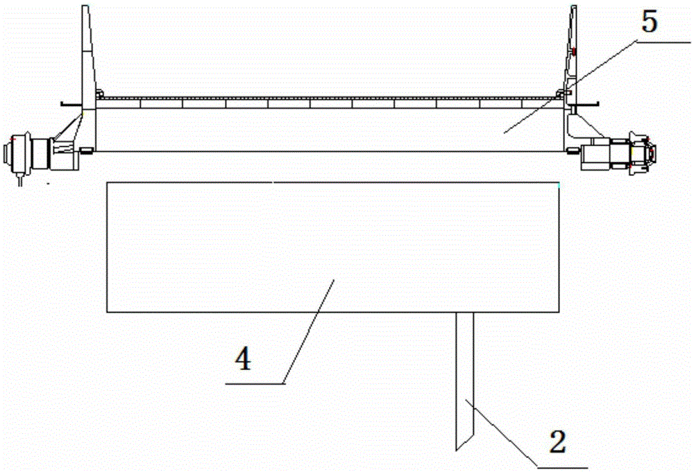
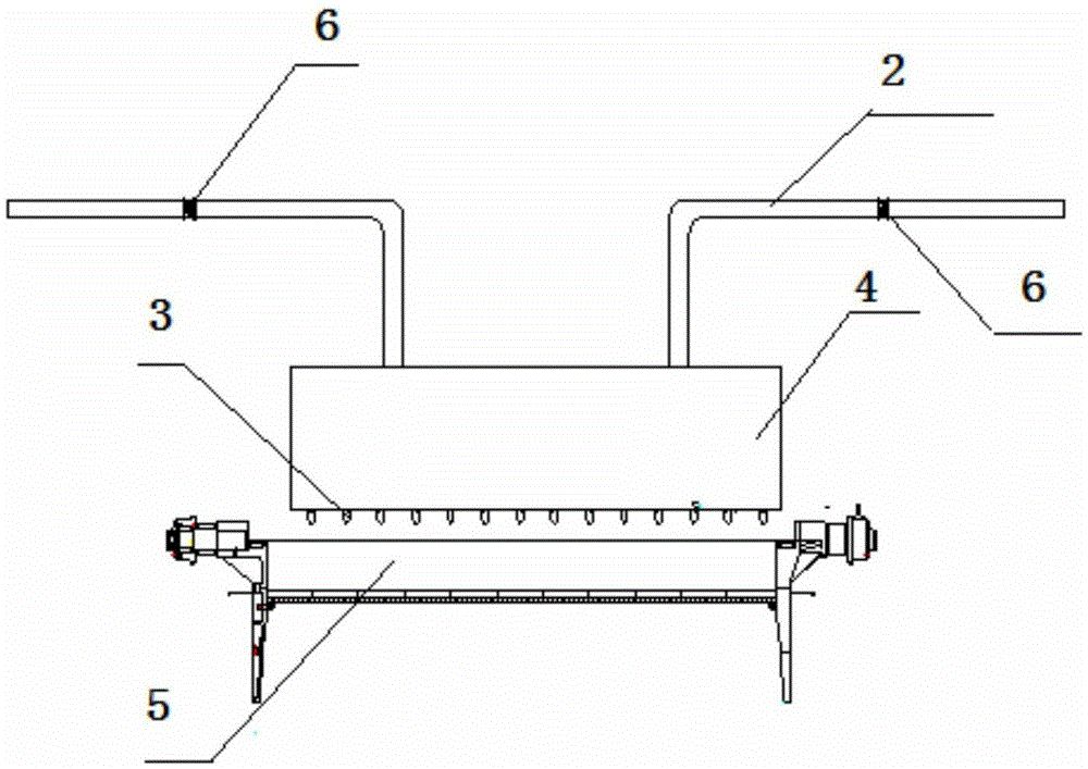
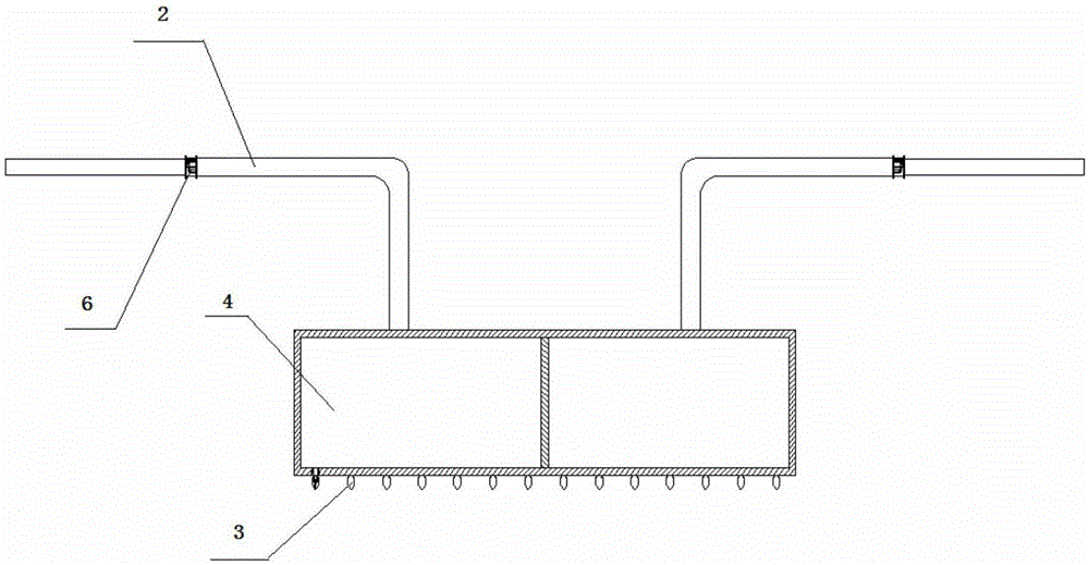
[0029] The present invention provides a material cleaning device for sintering machine trolley 5, such as figure 2 As shown, the cleaning device includes: a pressure vessel 1, a delivery pipeline 2, a purge head 3 and a purge device 4, the pressure vessel 1 communicates with the purge device 4 through the delivery pipeline 2, and...


PUM


Abstract

The invention discloses a material removal device for a sintering machine trolley. The material removal device comprises pressure containers (1), conveying pipelines (1), blowing heads (3) and a blowing device (4). The pressure containers (1) are communicated with the blowing device (4) through the conveying pipelines (2). The blowing heads (3) are arranged on the blowing device (4) and face the upper surface of the sintering machine trolley (5). The material removal device for the sintering machine trolley solves the problem that sinter particles cannot fall off from a sintering machine trolley in time in the prior art and guarantees that blown sinter particles fall off from the trolley in time.

Description

technical field [0001] The invention relates to the field of cleaning on a sintering machine trolley, in particular to a material cleaning device for a sintering machine trolley. Background technique [0002] The material cleaning device used for the sintering machine trolley in the prior art is mainly composed of four parts: a purging device, an air delivery pipeline system, a pressure vessel and a sintering machine trolley. The whole system is controlled by PLC. PLC controls the solenoid valve on the air delivery pipeline system. The solenoid valve switch controls the valve switch on the air delivery pipeline system. When the solenoid valve works, the compressed air in the pressure vessel starts to supply to the purging device. At this time, the compressed air is blown from the top of the purging device to the trolley, so as to play a role in purging. [0003] Such a method will make the blown sinter particles unable to fall from the sinter machine trolley in time, so des...

Claims


Application Information

Patent Timeline
Patent Type & Authority Applications(China)
IPC IPC(8): F27B21/08
Inventor 朱玉停王玉柱
Owner WUHU XINXING DUCTILE IRON PIPES
Why Eureka
Try Eureka