Eureka AIR delivers breakthrough ideas for toughest innovation challenges, trusted by R&D personnel around the world.

Mechanical steel bar equal-length cutting equipment

A technology of cutting equipment and steel bars, applied in the field of long cutting equipment, can solve the problems of low degree of automation, low work efficiency, insufficient control of cutting blades, etc., and achieve the effect of high degree of automation, large single workload and high work efficiency

Active Publication Date: 2020-07-10
陈思涵
View PDF7 Cites 0 Cited by
  • Summary
  • Abstract
  • Description
  • Claims
  • Application Information

AI Technical Summary

Problems solved by technology

When the equipment cuts the steel bars, it cannot cut a large number of steel bars at a time, and it cannot cut multiple sets of steel bars of different equal lengths at the same time. The control of the operation and stop of the cutting knife is insufficient, and the work efficiency is low. low degree of automation

Method used

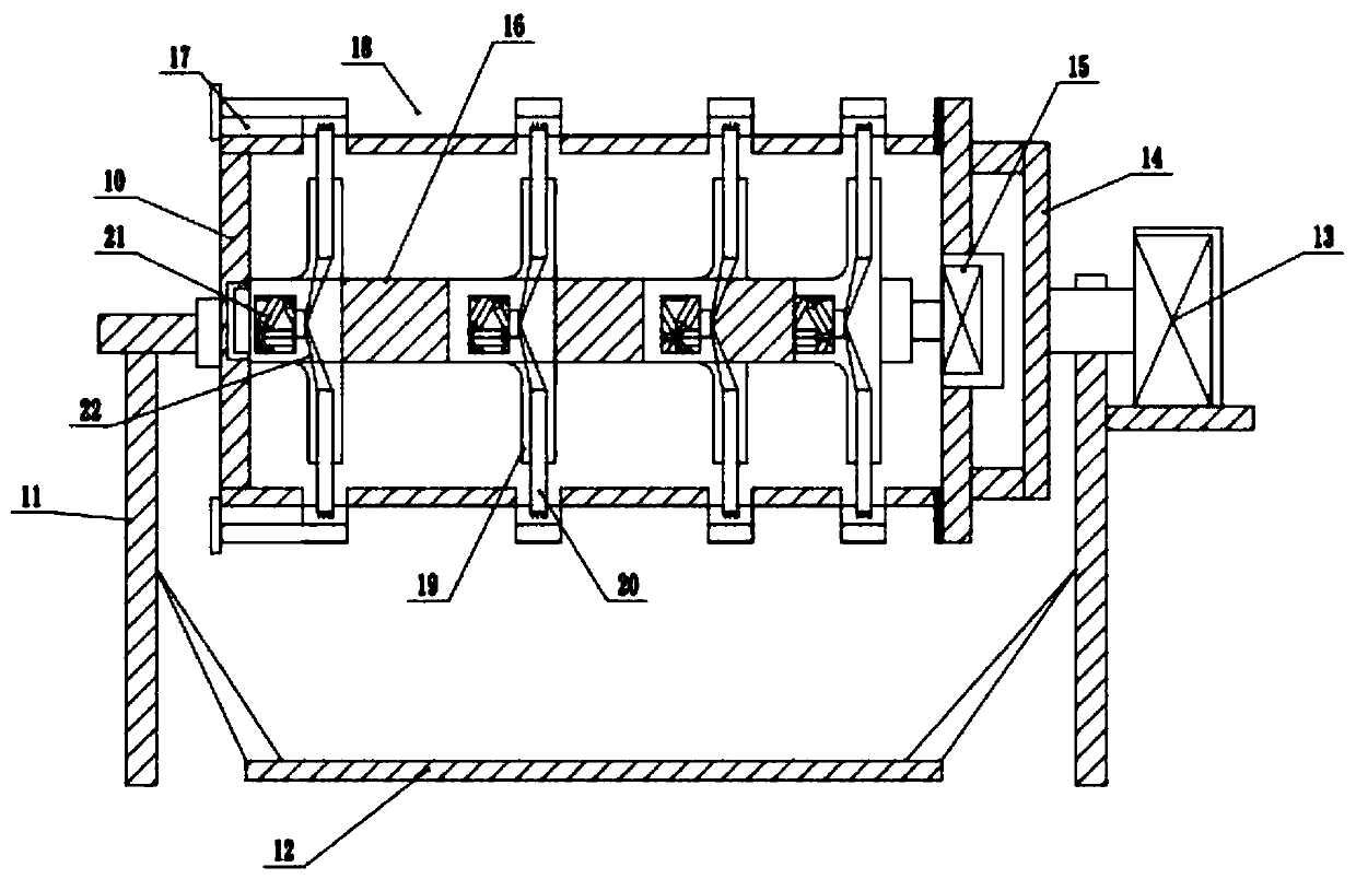
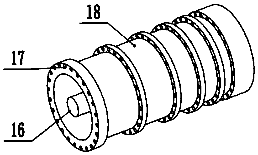

Image

  • Mechanical steel bar equal-length cutting equipment
  • Mechanical steel bar equal-length cutting equipment
  • Mechanical steel bar equal-length cutting equipment

Examples


Embodiment 1

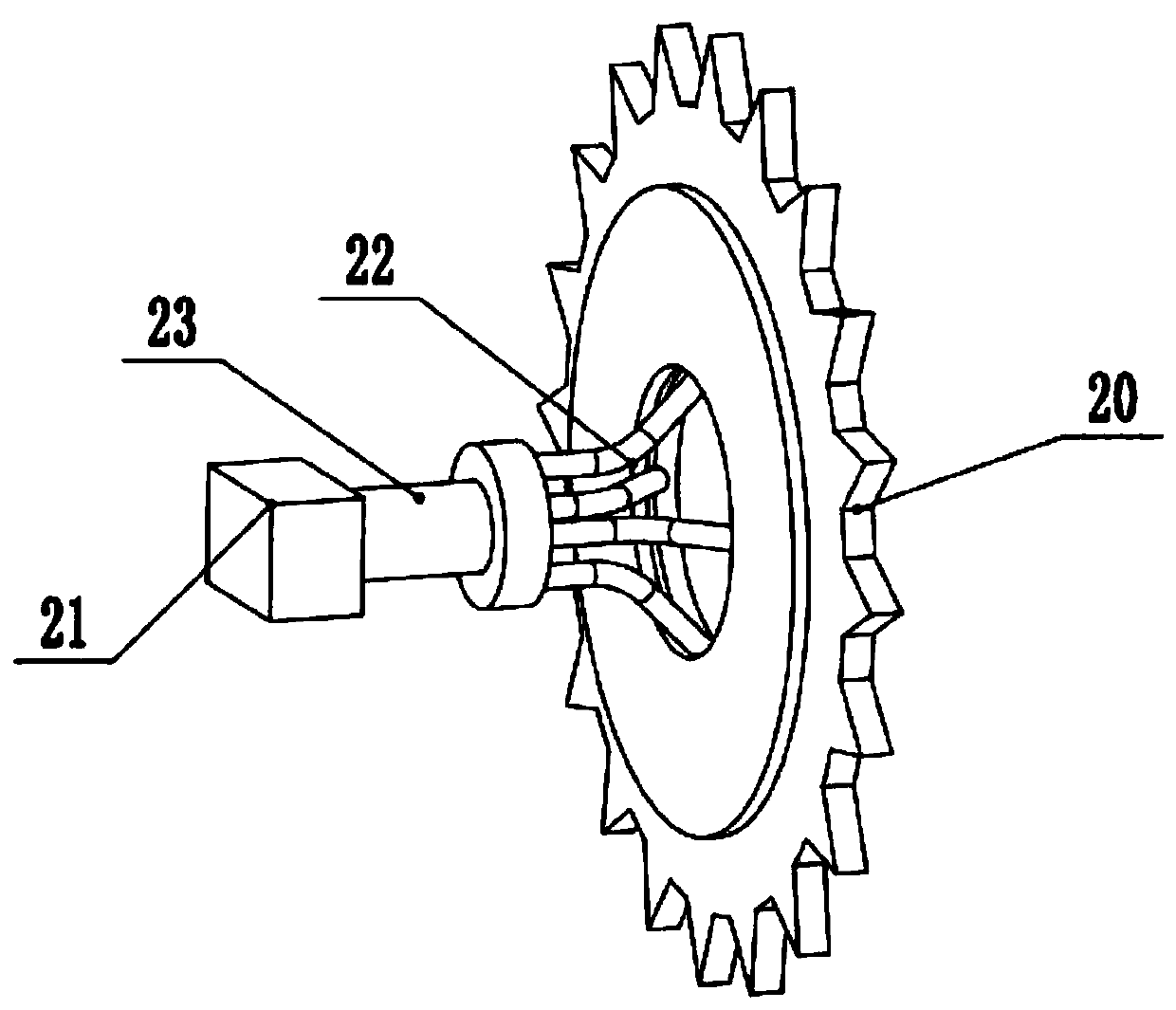
[0023] See Figure 1-3 , A mechanical steel bar isometric cutting equipment, including a pipe body 10, a collection tank 12, a first motor 13, a second motor 15, a steel bar input hole 17, a cutting knife 20; the left side of the pipe body 10 is connected with a rotating The bottom of the rotating seat is supported by the bracket 11. The right side of the tube body 10 is fixedly installed with a set of mounting brackets 14 in a U-shaped structure, and the middle of the right side of the mounting bracket 14 is fixedly installed with the tube core of the tube body 10. The rotating rods overlap each other. The right end of the rotating rod is rotatably connected with the first motor 13, the middle of the rotating rod is supported by the vertical bracket 11, and the bottom of the first motor 13 is supported by the support plate fixed on the bracket 11 at the left end. . A protective cover is provided on the outside of the first motor 13, and a sound insulation layer is provided on...

Embodiment 2

[0028] On the basis of the first embodiment, the inner side of the knife cavity 19 is pasted with a layer of rubber pad. When the telescopic rod 22 pulls the cutting knife 20 to expand, it is inevitable that the cutting knife 20 is arranged inside the knife cavity 19 It will come into contact with the knife cavity 19, and by providing a rubber pad, the cutting knife 20 and the knife cavity 19 can be prevented from being worn out during contact.


PUM


Abstract

The invention relates to the technical field of steel bar manufacturing equipment, and discloses mechanical steel bar equal-length cutting equipment. The mechanical steel bar equal-length cutting equipment comprises a pipe body, a collection trough, a first motor, a second motor, steel bar input holes and cutting knives. The multiple sets of transverse steel bar input holes at equal distance are formed in the outer side of the pipe body. Multiple sets of falling openings with lengths sequentially increased are formed on the steel bar input holes from right to left. Cutting troughs are downwards formed in the positions, between the falling openings, in the steel bar input holes. The cutting knives are rotationally connected in the cutting troughs. One set of cutting knives with diameters and sizes being telescopic are arranged in each knife cavity. The inner side of each cutting knife leftwards communicates with four sets of identical inclined telescopic rods, the left ends of the telescopic rods of each cutting knife are fixedly connected with a transverse piston rod through a connecting plate, air cylinders fixed in rotating shaft pipes are arranged on the left sides of the pistonrods, and the interiors of the cutting knives are connected through multiple sets of telescopic plates at equal distance. The mechanical steel bar equal-length cutting equipment has the advantages that the workloads of a single time are large, the automation degree is high, and the work efficiency is high.

Description

Technical field [0001] The invention relates to the technical field of steel bar manufacturing equipment, in particular to a machine-use steel bar isometric cutting equipment. Background technique [0002] Reinforcing steel refers to steel for reinforced concrete and prestressed reinforced concrete. Its cross-section is round and sometimes square with rounded corners. [0003] The Chinese patent (Announcement No.: CN 107813015 B, announcement date: 2019.04.09) provides such a mechanical steel bar isometric cutting equipment, including a bottom plate, a first support rod, a roller, a first transmission bar, and a second support rod , Guide sleeve, third support rod, etc.; the upper side of the bottom plate is connected with the first support rods on the left and right sides, the two first support rods are rotatably connected with rollers on the front side and the first transmission bar is connected between the two rollers , Rebar is placed on the first transmission bar, and a secon...

Claims


Application Information

Patent Timeline
IPC IPC(8): B21F11/00B21F23/00B65G47/74
CPCB21F11/00B21F23/00B65G47/74
Inventor 陈思涵郑清源
Owner 陈思涵
Why Eureka
Eureka Blog
Learn More