
Slag mechanism

A technology of impact mechanism and slag head, which is applied in the field of smelting equipment, can solve the problems of poor slag pounding effect, low tamping head insertion speed, and small impact force, etc., and achieve good slag pounding effect, guaranteed durability, and large impact effect

Inactive Publication Date: 2018-06-29
PANZHIHUA GUOTAI SCI & TECH
View PDF5 Cites 0 Cited by
  • Summary
  • Abstract
  • Description
  • Claims
  • Application Information

AI Technical Summary

Problems solved by technology

[0004] The main problem of the current slag breaking mechanism of the slag breaking machine is that due to the low extension speed of the telescopic oil cylinder, the insertion speed of the tamping head is also low, resulting in small impact force and poor slag breaking effect

Method used


Image

  • Slag mechanism

Examples


Embodiment Construction

[0014] The present invention will be further described below in conjunction with the accompanying drawings and embodiments.

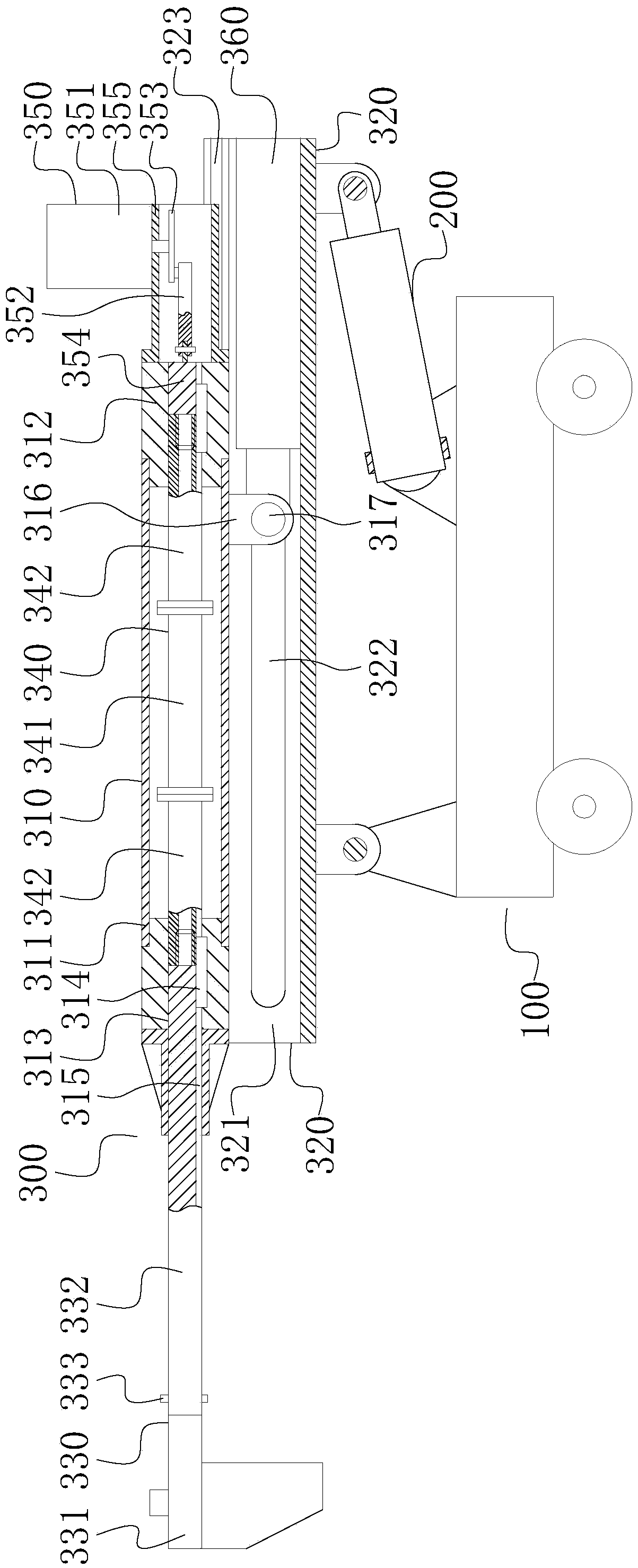
[0015] The slag breaking mechanism of the present invention includes a telescopic arm 310, a support arm 320, a tamping head 330, a guide rod 340, an impact mechanism 350, and a telescopic oil cylinder 360; The telescopic oil cylinder 360 is installed between the support arm 320 and the telescopic arm 310; the guide rod 340 is mounted on the telescopic arm 310 and is slidably matched with the telescopic arm 310; the ram 330 is mounted on one end of the guide rod 340; The mechanism 350 is installed on the telescopic arm 310 and connected with the other end of the guide rod 340 opposite to the ram 330 .

[0016] Such as figure 1 As shown, the slag breaking machine adopting the slagging mechanism of the present invention, when in use, the slagging mechanism 300 of the present invention is installed on the running gear 100 via the turning mechanism 200 . ...


PUM


Abstract

The invention relate to smelting equipment and particularly relates to a slag smashing mechanism. The slag smashing mechanism comprises a telescopic arm, a supporting arm, a smashing head, a guiding rod, an impacting mechanism and a telescopic cylinder, wherein the telescopic arm is mounted on the supporting arm and is matched with the supporting arm in a sliding manner, and the telescopic cylinder is mounted between the supporting arm and the telescopic arm; the guiding rod is mounted on the telescopic arm and matched with the telescopic arm in a sliding manner, the smashing head is mounted at one end of the guiding rod, and the impacting mechanism is mounted on the telescopic arm and connected with the other end, opposite to the smashing head, of the guiding rod. When the smashing head is in contact with caked furnace charges, vibration shocks are associated, the impacts are great, the slag smashing effect is good, and the slag smashing mechanism is far away from a furnace body, is good in durability and applicable to various submerged arc furnace slag smashing machines.

Description

technical field [0001] The invention relates to smelting equipment, in particular to a slag pounding mechanism. Background technique [0002] In the smelting process of the submerged arc furnace, it is necessary to smash the agglomeration of the furnace material, etc., and the traditional method is mainly manual. However, during the smelting process, the working environment near the submerged arc furnace is relatively harsh, and manual work is inefficient and dangerous. Therefore, a slag slag machine was developed for slag slag operations. [0003] The current slag breaking machine mainly includes a traveling mechanism, a turning mechanism, a slagging mechanism and a hydraulic system; the walking mechanism usually adopts a rail trolley; Installed between the track trolley and one end of the support arm, the other end of the support arm is hingedly installed on the track trolley, the support arm is driven to rotate around its hinge axis by the turning cylinder, the telescopi...

Claims


Application Information

Patent Timeline
Patent Type & Authority Patents(China)
IPC IPC(8): F27D25/00
CPCF27D25/001
Inventor 王世金张利明袁周云林朝飞
Owner PANZHIHUA GUOTAI SCI & TECH
Learn More