Wireless electromagnetic wave detection device

A detection device and radio technology, applied in the direction of electrical devices, measuring devices, electromagnetic field characteristics, etc., can solve the problems of narrow detection frequency band, high cost, low detection accuracy, etc., and achieve the effect of simple circuit, avoiding damage, and wide frequency band

Active Publication Date: 2016-02-24
WEIHAI BEIYANG ELECTRIC GRP CO LTD BEIJING BRANCH
View PDF6 Cites 1 Cited by
  • Summary
  • Abstract
  • Description
  • Claims
  • Application Information

AI Technical Summary

Problems solved by technology

[0006] In order to solve the technical problems of narrow detection frequency band, low detection accuracy and high cost of existing electromagnetic radiation detectors, the present invention provides a wireless electromagnetic wave detection device with wide detection frequency band, high detection accuracy and low cost

Method used


Image

  • Wireless electromagnetic wave detection device
  • Wireless electromagnetic wave detection device
  • Wireless electromagnetic wave detection device

Examples


Embodiment Construction

[0028] Referring to the accompanying drawings, the present invention will be further described in detail with specific embodiments.

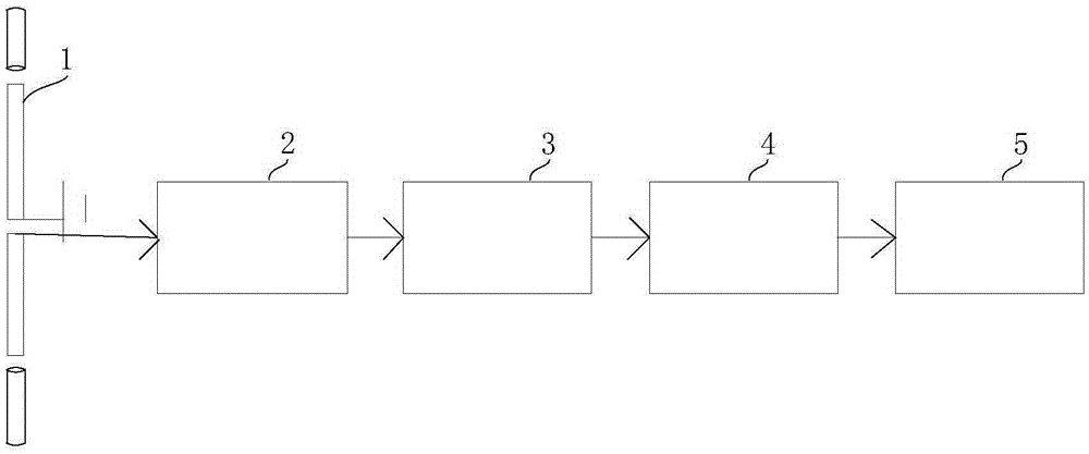
[0029] Such as figure 1 As shown, the wireless electromagnetic wave detection device of the present invention includes an antenna 1, a logarithmic power detector 2, a filter unit 3, a peak detection unit 4 and a single-chip microcomputer 5, and the output end of the antenna 1 is connected to the input end of the logarithmic power detector 2, The output end of the logarithmic power detector 2 is connected with the input end of the filter unit 3, the output end of the filter unit 3 is connected with the input end of the peak detection unit 4, and the output end of the peak detection unit 4 is connected with the input end of the single chip microcomputer 5. The single-chip microcomputer 5 may be connected with a display unit and a signal indication unit.

[0030] The essence of the radio wave detection of the wireless electromagnetic wave detectio...


PUM


Abstract

The invention relates to a wireless electromagnetic wave detection device, which solves the problems that the current electromagnetic wave detection device is narrow in the detection frequency band, low in the detection accuracy and high in the cost. The wireless electromagnetic wave detection device comprises an antenna, a logarithm power detection device, a filtering unit and a peak value demodulation unit; the output terminal of the antenna is connected to the input of the logarithm power detection device; the output terminal of the logarithm power detection device is connected to the peak value detection unit through the filtering unit. The invention is widely applicable to the radio wave detection technology field.

Description

technical field [0001] The invention relates to a detection device, in particular to a wireless electromagnetic wave detection device. Background technique [0002] In the field of radio wave detection technology, the existing electromagnetic radiation detector usually includes a radio frequency antenna, a high-speed operational amplifier peak detection circuit unit, a common operational amplifier signal amplification circuit unit and a DC output display circuit unit. [0003] Generally, for ultra-wideband radio frequency antennas, the relative area of ​​the antenna is required to be relatively large, in order to achieve a relatively flat input impedance change with the increase of frequency, that is, the bandwidth of the antenna is relatively wide. But a larger antenna will reduce the impedance and make the input signal low, which makes the detection inconvenient. The antenna settings of some radio wave radiation detectors obviously cannot achieve the required broadband eff...

Claims


Application Information

Patent Timeline
Patent Type & Authority Applications(China)
IPC IPC(8): G01R29/08G01R21/00
Inventor 刘春泽宋伟宁
Owner WEIHAI BEIYANG ELECTRIC GRP CO LTD BEIJING BRANCH
Why Eureka
Try Eureka