Wire detection method and system

A detection method and detection system technology, applied in the field of electromagnetic detection, can solve problems such as damage in the detection area, and achieve the effect of low cost and easy portability

Inactive Publication Date: 2016-02-24
UNIV OF SCI & TECH OF CHINA
View PDF6 Cites 2 Cited by
  • Summary
  • Abstract
  • Description
  • Claims
  • Application Information

AI Technical Summary

Problems solved by technology

On the one hand, this method confirms the position of the wire through contact detection, which is easy to cause certain damage to the detection area. On the other hand, it still requires manpower to draw the circuit distribution diagram

Method used


Image

  • Wire detection method and system
  • Wire detection method and system
  • Wire detection method and system

Examples


Embodiment 1

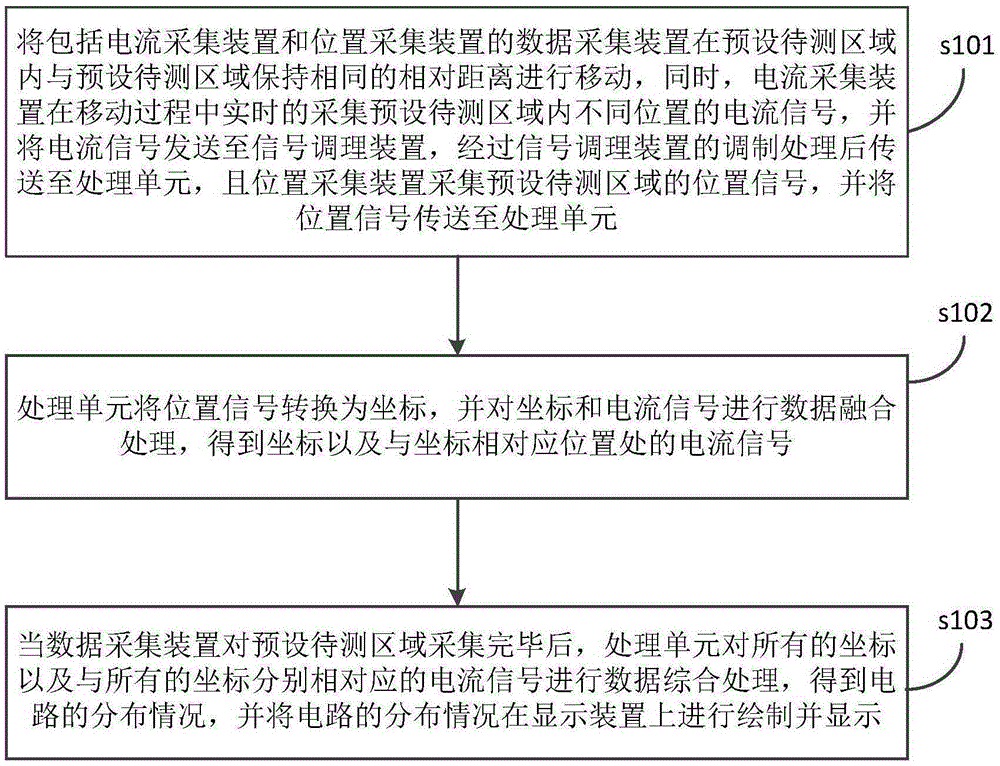
[0047] The invention provides a wire detection method, see figure 1 as shown, figure 1 A flow chart of the process of a wire detection method provided by the present invention; the method includes:

[0048]Step s101: Move the data acquisition device including the current acquisition device and the position acquisition device within the preset area to be measured at the same relative distance from the preset area to be measured, and at the same time, the current acquisition device collects and predicts in real time during the moving process Set the current signals of different positions in the area to be measured, and send the current signals to the signal conditioning device, and then transmit them to the processing unit after being modulated by the signal conditioning device, and the position acquisition device collects the position signals of the preset area to be measured, and sends The position signal is sent to the processing unit;

[0049] Step s102: the processing uni...
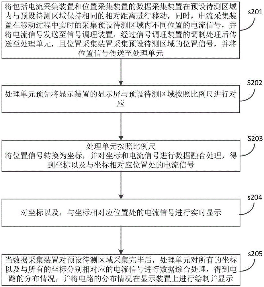
Embodiment 2

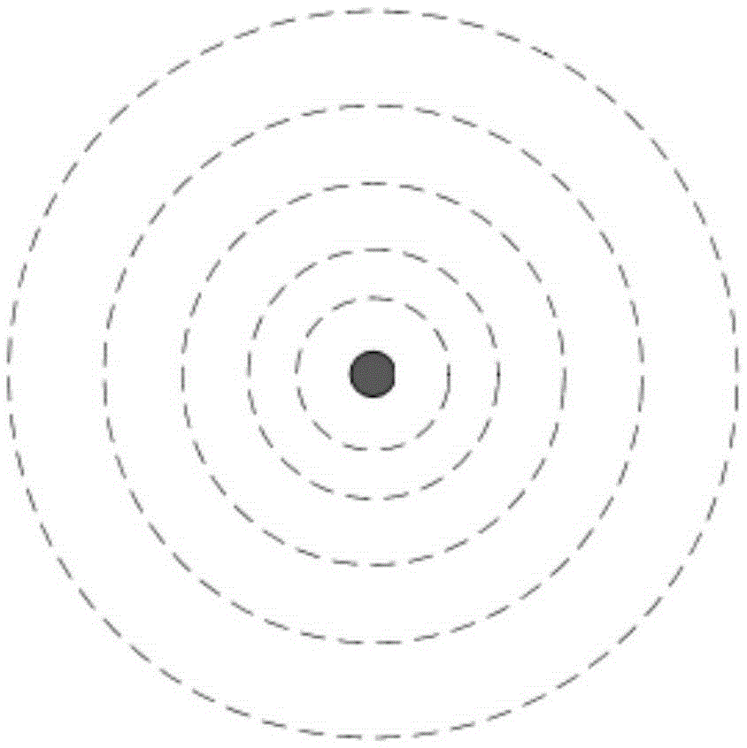
[0054] Based on the first embodiment, the present invention also provides another wire detection method, see figure 2 , image 3 , Figure 4 , Figure 5 and Figure 6 as shown, figure 2 A schematic diagram of the magnetic field around the wire in another wire detection method provided by the present invention; image 3 A flow chart of the process of another wire detection method provided by the present invention; Figure 4 A schematic diagram of an "S"-shaped preset detection trajectory in another wire detection method provided by the present invention; Figure 5 A schematic diagram of the corresponding relationship between the magnitude of the current signal and the position of the wire in the peak method in another wire detection method provided by the present invention; Figure 6 A schematic diagram of the corresponding relationship between the magnitude of the current signal and the position of the wire in the valley method in another wire detection method provided...


PUM


Abstract

The invention discloses a wire detection method and system, and the method comprises the steps: enabling a data collection device comprising a current detection apparatus and a position collection apparatus to move in a preset to-be-detected region, wherein the current detection apparatus collects current signals of different positions in the preset to-be-detected region in real time and transmits the current signals to a processing unit, and the position collection apparatus collects a position signal of the preset to-be-detected region and transmits the signal to the processing unit; converting the position signal into coordinates through the processing unit, carrying out data fusion of the coordinates and the current signals, and obtaining the coordinates and the current signals of positions corresponding to the coordinates; carrying out comprehensive processing of all coordinates and the current signal corresponding to the coordinates through the processing unit after the data collection apparatus collects the data of the preset to-be-detected region, obtaining a circuit distribution condition, and displaying the circuit distribution condition on a display apparatus. The system can carry out region detection in a non-damage manner, is low in cost, is portable, and can automatically complete the drawing of a circuit distribution map.

Description

technical field [0001] The invention relates to the technical field of electromagnetic detection, in particular to a wire detection method. The invention also relates to a wire detection system. Background technique [0002] In the current production and life, there are many conductive lines (such as circuits) buried in invisible places such as underground or inside walls, and workers often need to detect in order to determine the position of the wires. [0003] In the prior art, there are several detection methods for invisible wires as follows: [0004] Using the principle of electromagnetics for single-point detection, this method uses the characteristic of the induced magnetic field generated by the wire with alternating current around it to detect, which is more economical and convenient, but this method can only detect a certain point, but cannot For area detection, in addition, the detected position can only be recorded manually, and the drawing of the circuit distr...

Claims


Application Information

Patent Timeline
Patent Type & Authority Applications(China)
IPC IPC(8): G01V3/08
CPCG01V3/081
Inventor 陈欢欢周熙人胡云斌杨继伟
Owner UNIV OF SCI & TECH OF CHINA
Why Eureka
Try Eureka