A communication method, device and system
A communication method and communication device technology, applied in the field of communication
- Summary
- Abstract
- Description
- Claims
- Application Information
AI Technical Summary
Problems solved by technology
Method used
Image
Examples
Embodiment 1
[0047] The above is only a specific embodiment of the present invention, but the scope of protection of the present invention is not limited thereto. Anyone skilled in the art can easily think of changes or substitutions within the technical scope disclosed in the present invention. Should be covered within the protection scope of the present invention. Therefore, the protection scope of the present invention should be based on the protection scope of the claims.
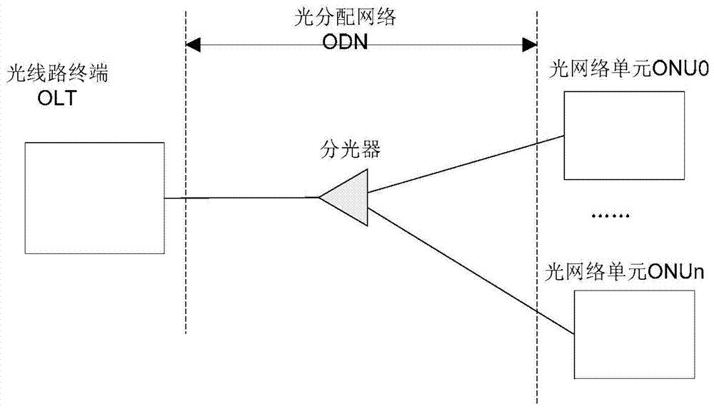
[0048] Such as figure 1 As shown, the passive optical network (Passive Optical Network, PON) consists of an optical line terminal (Optical Line Terminal, OLT) at the office side, an optical network unit (Optical Network Unit, ONU) at the user side, or an optical network terminal (Optical Network Terminal) , ONT) and Optical Distribution Network (Optical Distribute Network, ODN). At present, representative PON technologies are GPON (Gigabit-Capable Passive Optical Network, Gigabit Passive Optical Network), EPON (Et...
Embodiment 2
[0090] The embodiment of the invention also discloses a communication device, such as Figure 11 shown, including:
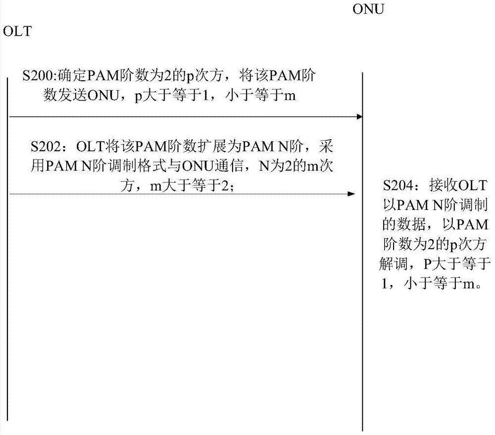
[0091] The processing unit 110 is configured to determine that the PAM order of the pulse amplitude modulation is F, and F is the p power of 2, and 1≤p≤m; it is also used to extend the determined PAM order F to PAM N-order modulation;
[0092] The sending unit 120 is configured to feed back the PAM order F to the optical network unit ONU; communicate with the ONU in an extended PAM N-order modulation format.
[0093] Optionally, the processing unit 110 is further configured to extend the PAM 2-level coding to PAM N-level coding to realize the registration of the ONU. Wherein, the processing unit 110 is also used to extend the PAM 2-level coding to PAM N-level coding to realize the registration of the ONU, specifically including expanding each bit in the data stream to m bits, and extending the second bit to the mth bit The bits are all the same as the first bi...
Embodiment 3
[0097] The embodiment of the present invention also discloses a communication device, such as Figure 12 shown, including:
[0098] The receiving unit 122 is configured to receive the pulse amplitude modulation PAM order sent by the optical line terminal OLT as F, where F is the P power of 2, where p is an integer greater than or equal to 1 and less than or equal to m; receive the pulse amplitude modulation PAM sent by the OLT The data modulated by PAM-N order, where N is 2 to the mth power, where m is an integer greater than or equal to 2;
[0099] The processing unit 124 is configured to use the PAM order of the pulse amplitude modulation as F to demodulate the PAM-N order modulated data sent by the OLT, where p is an integer greater than or equal to 1.
[0100] Optionally, the processing unit 124 is further configured to extend PAM level 2 encoding to PAM level N encoding registration, where N is 2 to the m power, where m is an integer greater than or equal to 2. Specific...
PUM
 Abstract
Description
Claims
Application Information
 - R&D
- Intellectual Property
- Life Sciences
- Materials
- Tech Scout
- Unparalleled Data Quality
- Higher Quality Content
- 60% Fewer Hallucinations
Browse by: Latest US Patents, China's latest patents, Technical Efficacy Thesaurus, Application Domain, Technology Topic, Popular Technical Reports.
© 2025 PatSnap. All rights reserved.Legal|Privacy policy|Modern Slavery Act Transparency Statement|Sitemap|About US| Contact US: help@patsnap.com


