Polarization modulator and method for beam polarization modulation

A polarization modulator and polarization modulation technology, which is applied in optics, instruments, optical components, etc., can solve the problem of low damage threshold and achieve the effects of high flexibility, convenient operation, and easy implementation

Pending Publication Date: 2018-01-30
LASER FUSION RES CENT CHINA ACAD OF ENG PHYSICS
View PDF4 Cites 0 Cited by
  • Summary
  • Abstract
  • Description
  • Claims
  • Application Information

AI Technical Summary

Problems solved by technology

At present, the traditional polarization modulation technology is usually accompanied by amplitude or phase modulation, while using liquid crystal technology to change the polarization state of different positions of the light field through electric drive, this technology has the problem of low damage threshold, so , the pure polarization modulation technology for the light field is still in the research stage

Method used


Image

  • Polarization modulator and method for beam polarization modulation
  • Polarization modulator and method for beam polarization modulation

Examples


Embodiment 1

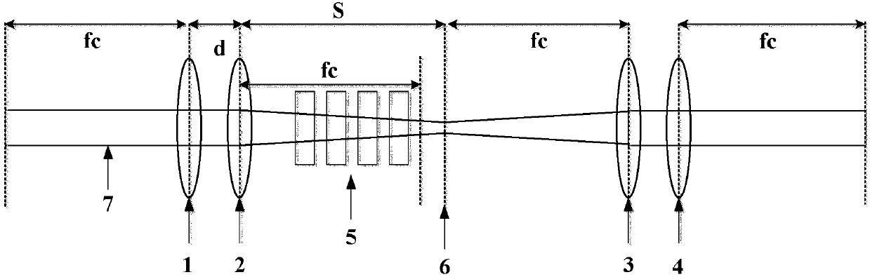
[0028] Such as figure 1 As shown, a polarization modulator includes a first focusing element group, a cascaded biaxial crystal group 5 and a second focusing element group, the first focusing element group and the second focusing element group are arranged on the same optical axis, and the two Both have the same structure, and both have a focusing function on the incident light beam 7 . The incident light beam 7 of a single polarization state is focused by the first focusing element group, then passes through the cascaded biaxial crystal group 5, and forms a hollow ring-shaped beam at the focal image plane 6 of the cascaded biaxial crystal group, and the ring-shaped beam passes through the second focusing After the element group, its light field intensity distribution is consistent with the incident light beam 7, and the polarization state is periodically distributed.

[0029] The first focusing element group includes a focal length f 1 The first optical element 1 and focal l...

Embodiment 2

[0032] A method for beam polarization modulation using a polarization modulator, comprising the steps of:

[0033] S1: The incident beam 7 enters the cascaded biaxial crystal group 5 through the first focusing element group, and adjusts the placement angle of the biaxial crystal through the crystal attitude adjustment frame, so that the wave normal optical axis of the biaxial crystal is parallel to the incident beam 7 , the incident beam 7 forms a hollow annular beam at the focal image plane 6 of the cascaded biaxial crystal group;

[0034] S2: According to the expected polarization modulation result, that is, the polarization distribution period of the beam, rotate the biaxial crystal with the transmission direction of the incident beam 7 as the axis, adjust the pseudo vector direction of each biaxial crystal, and promote the pseudo vector between adjacent biaxial crystals. vector angle, the annular beam is output through the second focusing element group to obtain the output...

Embodiment 3

[0040] The same part of this embodiment and embodiment two will not be repeated, the difference is:

[0041] The incident light beam 7 is circularly polarized Gaussian light, its wavelength is λ=532mm, and its beam waist radius is ω 0 =1mm, the focal length f of the first focusing element group and the second focusing element group c =200mm, there are 2 biaxial crystals in the cascaded biaxial crystal group 5, and the length of the biaxial crystals is l 1 = l 2 =5mm, the biaxial crystal material is KGW crystal, and its refractive index to the incident beam 7 is n 1 =2.013,n 2 =2.045, n 3 =2.086, the distance between the focal image plane 6 of the cascaded biaxial crystal group and the first focusing element group is S=205mm, and the distance between the first focusing element group and the second focusing element group is 405mm.

[0042] The output beam remains Gaussian, with a beam waist radius ω 0 =1mm, the light field intensity distribution remains unchanged. The pol...


PUM


Abstract

The invention, which belongs to the technical field of laser polarization modulation, relates to a polarization modulator and a method for beam polarization modulation. The polarization modulator comprises a first focusing element group, a cascaded biaxial crystal group and a second focusing element group. The cascaded biaxial crystal group is arranged between the first focusing element group andthe second focusing element group and a focal image plane of the cascaded biaxial crystal group is overlapped with the focal plane of the second focusing element group. The cascaded biaxial crystal group consists of at least two biaxial crystals and a pseudo-vector included angle is formed between the adjacent biaxial crystals. According to the invention, on the premise that the intensity distribution of the light field is not changed, only the polarization state of the beam is modulated and the polarization state distribution of the beam after modulation is in a periodic state; continuous modulation of the distribution period of the polarization state of the beam is realized by adjusting the focal lengths of the first focusing element group and the second focusing element group and changing the pseudo-vector included angle between the adjacent biaxial crystals; the flexibility is high; the whole modulation process is operated conveniently; and the method is easy to implement.

Description

technical field [0001] The invention belongs to the technical field of laser polarization modulation, and in particular relates to a polarization modulator and a beam polarization modulation method. Background technique [0002] Due to the continuous development of laser technology and its applications, laser spatial modulation technology has attracted more and more attention. In the field of traditional laser communication transmission, the light intensity, frequency, polarization, phase and other characteristics of the beam can be used as an information carrier. Spatial light modulation technology can change the phase, polarization, amplitude distribution and wavelength information of spatial light under the control of electric drive that changes with time, or under the action of another spatial intensity distribution, so as to load information into the optical data field. Therefore, it is widely used in data storage, information transmission, etc. Currently existing spa...

Claims


Application Information

Patent Timeline
Patent Type & Authority Applications(China)
IPC IPC(8): G02B27/28
Inventor 孙喜博耿远超刘兰琴黄晚晴张颖王文义朱启华胡东霞袁强邓学伟杨英周丽丹
Owner LASER FUSION RES CENT CHINA ACAD OF ENG PHYSICS
Why Eureka
Try Eureka