
A uniform low-loss air path system and air flow organization method for a pneumatic seeder

An air system and air pressure technology, applied in the field of agricultural machinery, can solve the problems of uneven air distribution, large difference in the working effect of seed metering devices, and large air flow loss, etc., and meet the requirements of ensuring air tightness, high consistency, The effect of less air loss

Active Publication Date: 2017-05-31
CHINA AGRI UNIV
View PDF8 Cites 0 Cited by
  • Summary
  • Abstract
  • Description
  • Claims
  • Application Information

AI Technical Summary

Problems solved by technology

[0003] Pneumatic seeders require fans to provide sufficient air pressure and air volume to ensure the normal operation of the seeder. Existing pneumatic seeder fans are generally driven by tractor power output shafts or tractor hydraulic systems, and adopt straight pipe air system Airflow distribution, that is, one airflow inlet and multiple airflow outlets are set on a straight pipe. Due to the right-angle relationship between the outlet and the inlet, the airflow loss is large, and the airflow of each branch air path is uneven due to the uneven distance between the airflow inlet and the airflow inlet. Uneven distribution, resulting in large differences in the working effect of individual seed meters in each row

Method used


Image

  • A uniform low-loss air path system and air flow organization method for a pneumatic seeder
  • A uniform low-loss air path system and air flow organization method for a pneumatic seeder
  • A uniform low-loss air path system and air flow organization method for a pneumatic seeder

Examples


Embodiment Construction

[0058] The present invention is further described below in conjunction with embodiment.

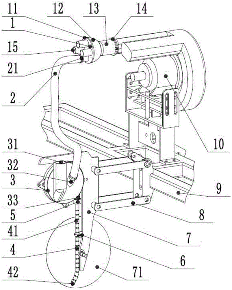
[0059] Such as figure 1 As shown, the uniform low-loss air path system of the pneumatic seeder of the present invention includes a vortex fan 10 , an air distributor 1 , an air hose 2 , a pneumatic seed meter 3 and a seed pipe 4 . Wherein, the vortex blower 10 is fixedly connected on the frame 9 .

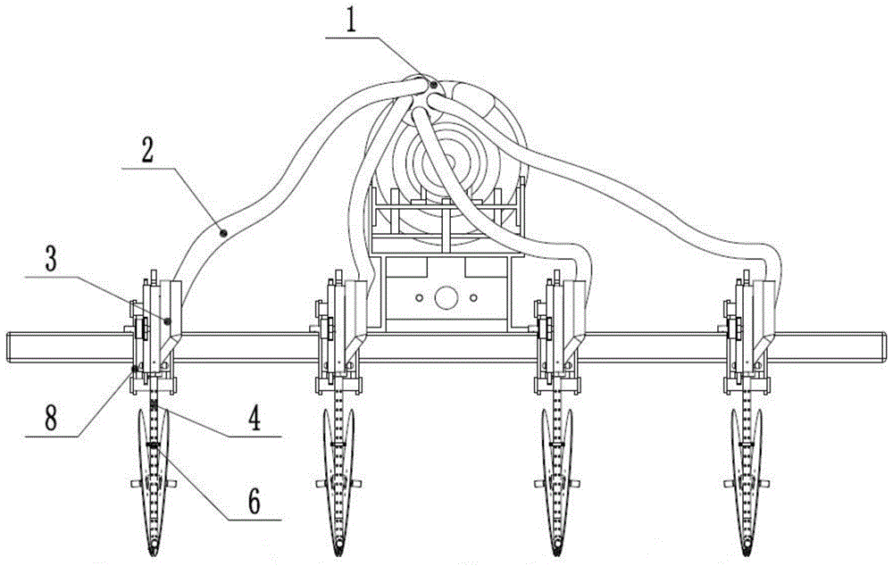
[0060] Such as figure 2 As shown, the seed metering unit composed of the pneumatic seed metering device 3 and the seed metering pipe 4 is fixedly connected to the frame 9 through the seed metering unit plate 7 and the parallel four-bar linkage mechanism 8 . Multiple groups of seed metering units are evenly and equidistantly distributed to both sides with the central axis of the vortex fan 10 as the center. Preferably, the number of seeding monomers is four groups.

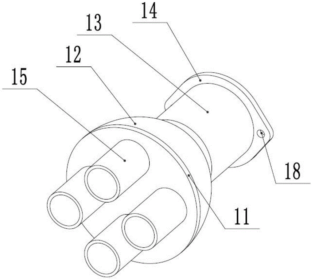
[0061] Such as image 3 with Figure 4 As shown, the airflow distributor 1 includes a distributor disk 11, a reducing join...


PUM


Abstract

The invention belongs to the field of agricultural machinery and relates to a uniform and low-loss air path system and an air flow organization method for a pneumatic seeder. The airflow enters the air inlet pipe (13) of the airflow distributor (1), passes through the reducing joint (12), and is divided into multiple airflow paths with the same size by multiple air outlet pipes (15) evenly distributed on the distributor circular plate (11). The airflow then enters the seeding pipe (4) through the pneumatic seeding device (3). Every time it drops to a certain height, the airflow is gradually discharged from the air vents (41) evenly arranged on the body of the seeding pipe (4), and the seeding pipe (4) The air flow pressure in 4) gradually decreases, and the speed of the seeds falling with the air flow decreases significantly, and is finally discharged from the seed discharging pipe outlet (42). The uniform and low-loss air path system of the pneumatic seeder of the present invention can effectively make the air supply pressure of the individual seed metering devices consistent for each row of seeding, reduce the power demand of the fan by reducing the loss caused by the gas distribution process, and at the same time increase the leakage of the seed metering process. The pressure significantly reduces the seeding speed of the pneumatic seed metering device.

Description

technical field [0001] The invention belongs to the field of agricultural machinery, and in particular relates to a uniform low-loss air path system and an air flow organization method for a pneumatic seeder. Background technique [0002] In recent years, pneumatic precision corn seeding technology has been widely used in my country. The pneumatic seeder can realize high-speed sowing operation and can effectively improve the operation efficiency. The sowing effect of the pneumatic corn precision seeder mainly depends on the quality of the seed meter, but whether the pneumatic seed meter can work normally depends on the air system of the seeder. For pneumatic seeders, whether the seeding performance of individual seed metering devices in each row is consistent is closely related to the uniformity of air distribution in the air system. [0003] Pneumatic seeders require fans to provide sufficient air pressure and air volume to ensure the normal operation of the seeder. Exist...

Claims


Application Information

Patent Timeline
Patent Type & Authority Patents(China)
IPC IPC(8): A01C7/18A01C7/20
CPCA01C7/18A01C7/20A01C7/206A01C7/084
Inventor 杨丽殷小伟张东兴崔涛韩丹丹张瑞张天亮王满涛和贤桃李克鸿颜丙新屈哲刘全威赵东岳虞异茗
Owner CHINA AGRI UNIV
Learn More