
Welding process for ball mill seal head end cover

A welding process and ball mill technology, applied in welding equipment, welding accessories, manufacturing tools, etc., can solve the problems of workers' operation failing to meet uniform standards, head quality not meeting requirements, and welding quality instability, etc., so as to facilitate placement Positive placement, easy indexing and positioning, and simple actions

Inactive Publication Date: 2016-03-02
淄博大工机械有限公司
View PDF5 Cites 4 Cited by
  • Summary
  • Abstract
  • Description
  • Claims
  • Application Information

AI Technical Summary

Problems solved by technology

At present, in the welding process of the head end cover of the ball mill, in order to shorten the process as much as possible, the manual one-time welding process is basically adopted. When welding the rib plate, reinforcement plate, main shaft and end cover of the head, the workers manually position each The parts are completely welded, the operation of the workers does not meet the uniform standards, the welding efficiency is low, and the welding quality is unstable
With the development of society, the disadvantages of manual welding are also becoming more and more obvious, such as many welding layers, many pores, and long welding time, resulting in the quality of the welded head not meeting the requirements and causing greater losses.
At present, there is a lack of a suitable process flow, so that the welding of the end cover of the ball mill can adapt to the automatic process to improve production efficiency

Method used


Image

  • Welding process for ball mill seal head end cover
  • Welding process for ball mill seal head end cover

Examples


Embodiment 1

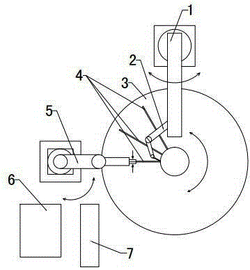
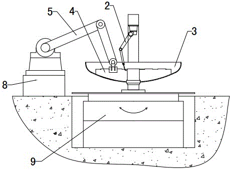
[0024] 1) First, install and fix the head end cap with the opening facing up on the vertical welding positioner through the main shaft passing through the head end cap; use the handling robot to transfer the ribs in the turnover box and place them in the head end cap At the same time, use the welding robot for gas shielded welding to perform spot welding positioning at the contact point between the rib plate and the end cover, and the contact point between the rib plate and the main shaft; start the welding positioner to rotate 20°, and then move the robot Another rib is placed in the next position to be welded in the head end cover, and the above operation is repeated until all the designed number of ribs of the head end cover are spot welded;

[0025] 2) Buckle the head end cover with the rib plate spot welded downwards on the flat workbench, and then put the reinforcement plate with the same arc as the head end cover on the main shaft outside the head end cover, the reinforc...

Embodiment 2

[0028] 1) Firstly, install and fix the head end cover with the opening facing up on the vertical welding positioner through the main shaft passing through the head end cover; use the handling robot to transfer the rib plate in the rib plate turnover box to the head end At the position to be welded in the cover, at the same time, use the welding robot for gas shielded welding to perform spot welding positioning at the contact point between the rib plate and the end cover, and the contact point between the rib plate and the main shaft; start the welding positioner to rotate 30°, and move the robot Then place another rib plate at the next position to be welded in the head end cover, and repeat the above operation until all spot welding of the designed number of rib plates of the head end cover is completed;

[0029] 2) Buckle the head end cover with the rib plate spot-welded downwards on the flat workbench, then put the reinforcing plate with the same arc as the head end cover on ...

Embodiment 3

[0032]1) Firstly, install and fix the head end cover with the opening facing up on the vertical welding positioner through the main shaft passing through the head end cover; use the handling robot to transfer the rib plate in the rib plate turnover box to the head end At the position to be welded in the cover, at the same time, use the welding robot for gas shielded welding to perform spot welding positioning at the contact point between the rib plate and the end cover, and the contact point between the rib plate and the main shaft; start the welding positioner to rotate 18°, and move the robot Then place another rib plate at the next position to be welded in the head end cover, and repeat the above operation until all spot welding of the designed number of rib plates of the head end cover is completed;

[0033] 2) Buckle the head end cover with the rib plate spot welded downwards on the flat workbench, and then put the reinforcement plate with the same arc as the head end cove...


PUM


Abstract

The invention belongs to the technical field of tank welding, and relates to a welding process for a ball mill seal head end cover. The welding process for the ball mill seal head end cover is characterized by including the welding steps that indexing tack welding is carried out on rib plates and a seal head end cover through welding robots; a reinforcing plate is welded to a main shaft of the seal head end cover through the welding robots; the main shaft, provided with the reinforcing plate in a welded mode, of the seal head end cover is relatively clamped fixedly through a welding positioner arranged horizontally and a clamping part, and all the rib plates are welded in a sealed mode through the welding robots. The welding process of the whole seal head end cover can be implemented in a streamline mode, the production efficiency of the seal head end cover is greatly improved, the welding quality of the seal head end cover is greatly improved while the uniform product specification is ensured, the one-time qualified rate is increased, and the service life of a ball mill is prolonged.

Description

technical field [0001] The invention relates to a ball mill head end cover welding process, which belongs to the technical field of tank body welding. Background technique [0002] The end cover of the ball mill head is the main part of the ball mill. The main shaft at the center of the end cover of the ball mill is the key part for the connection and transmission of the ball mill and the power device of the ball mill. The firmness and accuracy of the welding of the main shaft directly determine the functions and service life. At present, in the welding process of the head end cover of the ball mill, in order to shorten the process as much as possible, the manual one-time welding process is basically adopted. When welding the rib plate, reinforcement plate, main shaft and end cover of the head, the workers manually position each The parts are completely welded, the operation of the workers cannot meet the uniform standards, the welding efficiency is low, and the welding qua...

Claims


Application Information

Patent Timeline
Patent Type & Authority Applications(China)
IPC IPC(8): B23K9/16B23K9/12B23K9/32
CPCB23K9/16B23K9/12B23K9/32
Inventor 梁欣顺张先淼毕延坤李太祥鄂冠达
Owner 淄博大工机械有限公司
Learn More