Cotton web bundling mechanism of intelligent comber

A comber, intelligent technology, applied in the direction of comber, textile and papermaking, fiber processing, etc., can solve the problem of affecting the normal operation of the sliver quality, not effectively improving the cohesion of the sliver, and adversely affecting the mutual interaction of the sliver. Cohesion and other problems, to achieve the effect of convenient sliver accumulation, not easy to loosen, and convenient for subsequent maintenance

Active Publication Date: 2016-03-02
JIANGSU KAIGONG MACHINERY
6 Cites 1 Cited by

AI-Extracted Technical Summary

Problems solved by technology

In the currently adopted cotton web bundling scheme, in order to assist the conveying of the sliver inside the guide tube, a blowing nozzle is installed on the guide tube, and the sliver reaches the common bell mouth through the guide tube, and then reaches the pressure roller through the bell mouth And the clamping point of the conveyor belt, due to the winding pressure roller of the conveyor belt part, the sliver is loaded with a pressing force, which produces a slight compression on the sliver, so that the sliver is flattened and...

Method used

Also be provided with a pressurization bar 9 and pressurization driving device 11, pressurization bar 9 is hinged on the intelligent combing machine support 8, the second pressure roller can rotate and be located at pressurization bar 9 one ends, pressurization drive unit 11 can drive the pressure rod 9 to rotate around the hinge shaft, the intelligent comber control unit controls the action of the pressure driving device 11, and the movement of the pressure rod 9 drives the second pressure roller to approach or leave the first pressure roller, which is convenient for maintenance.
Described intelligent combing machine support 8 is fixedly provided with fixed shaft 7, gathers tube 1 side wall and is provided with and gathers the positioning hole perpendicular to...

Abstract

The invention discloses a cotton web bundling mechanism of an intelligent comber. The cotton web bundling mechanism adopts the structure that a first press roller and a second press roller on a supporting seat of the intelligent comber are mutually meshed for transmission; a driving device drives the first pressure roller to rotate; the inlet of a gathering pipe is just positioned behind a drafting output roller; the inlet of a conveying pipe is fixedly communicated with the outlet of the gathering pipe; a bundling horn mouth is fixedly mounted on the supporting seat of the intelligent comber; the inlet of the bundling horn mouth can be communicated with the outlet of the conveying pipe; a horn hole of which the outlet diameter is smaller than the inlet diameter is formed in the inner side of the bundling horn mouth; the meshing point between the first and second press roller just faces the outlet of the bundling horn mouth; a flat groove is formed in the side wall positioned at the outlet end of the bundling horn mouth; the mutually meshed ends of the first and second press rollers are just inserted into the flat groove; the meshing point between the first and second press roller is just positioned in the flat groove. Through adoption of the cotton web bundling mechanism, the cohesive force of gathered cotton slivers is remarkably improved, so that the cotton slivers are not easy to loosen when being conveyed on a conveying belt and not easy to break at a turning point, and then high-speed conveying and convenient maintenance of the cotton silvers are facilitated.

Application Domain

Combing machines

Technology Topic

Image

  • Cotton web bundling mechanism of intelligent comber
  • Cotton web bundling mechanism of intelligent comber
  • Cotton web bundling mechanism of intelligent comber

Examples

  • Experimental program(1)

Example Embodiment

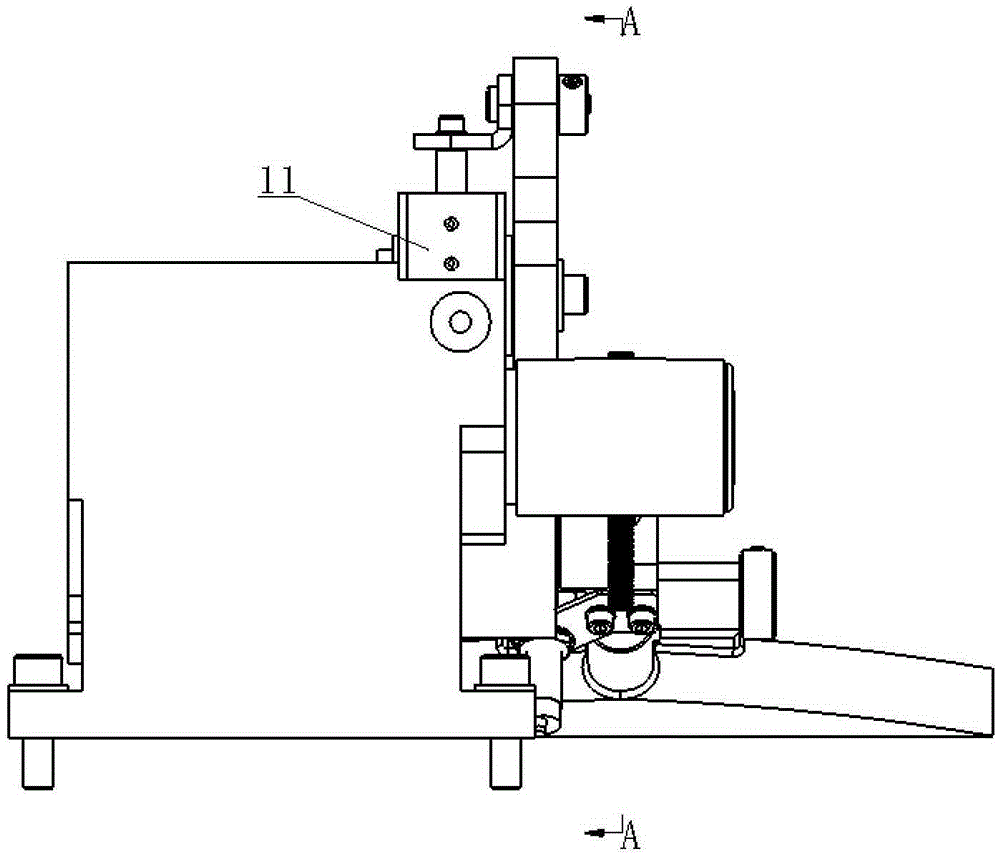
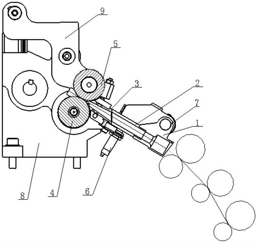
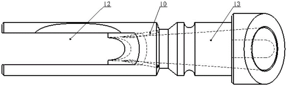
[0020] Embodiment: A cotton web bundling mechanism of an intelligent combing machine, including first and second pressure rollers 4, 5, a driving device, a gathering pipe 1, a conveying pipe 2, and a gathering horn positioned on the support 8 of the intelligent combing machine Port 3, the first and second pressure rollers 4, 5 mesh with each other, the driving device drives the first pressure roller to rotate, the inlet of the gathering tube 1 is just behind the drafting output roller of the intelligent combing machine, the inlet of the conveying tube 2 and the gathering tube 1 The outlet is fixed and connected, and the cluster horn 3 is fixedly installed on the support 8 of the smart comber. The inlet of the cluster horn 3 can be communicated with the outlet of the conveying pipe 2. The inner side of the cluster horn 3 is a horn hole 13 whose outlet diameter is smaller than the inlet diameter. , The first and second pressure rollers 4, 5 meshing points are directly opposite to the outlet of the cluster bell mouth 3, the cluster bell mouth 3 is located on the side wall of the outlet end formed with a flat groove 12, the first and second pressure rollers 4, 5 mutually The meshing side is just inserted into the flat groove 12, and the meshing point is just inside the flat groove 12. When working, the first and second pressure rollers 4 and 5 are driven by the driving device to engage and drive to realize the transmission of the sliver. The cotton net output by the mechanism is conveyed to the cluster bell mouth 3 through the gathering pipe 1 and the conveying pipe 2. The inner hole of the gathering bell mouth 3 adopts the horn hole 13 to facilitate the gathering and guiding of the sliver, and the outlet diameter can be changed according to the thickness of the sliver. Different values, the value range is 4-7mm, the first and second pressure rollers 4 and 5 with the same tooth profile in the flat groove 12 on the upper side of the small outlet of the cluster bell mouth 3 mesh with each other, and the two walls of the flat groove 12 prevent the sliver Stretching outwards from the side, the sliver can be compressed across the entire cross-section, the sliver can be entangled for the second time, and the sliver can be transported. The web bundling mechanism of the smart comber significantly improves the gathering The cohesive force of the sliver makes the sliver not easy to loosen during the conveying process on the conveyor belt, and it is not easy to break the sliver at the turning point of the sliver, which is beneficial to the high-speed conveying of the sliver.
[0021] The width of the flat groove 12 is 7-11mm, and the width of the flat groove 12 on the upper side of the outlet of the clustered bell mouth 3 (3) is 1mm larger than the thickness of the teeth of the pressing wheel. When the first and second pressing rollers 4 and 5 are engaged, the wheel The teeth are centered in the flat groove 12 along the thickness direction, so that the first and second pressure rollers 4 and 5 with the same tooth profile mesh and drive each other, and the first and second pressure rollers 4 and 5 press uniformly indentation on the sliver, flat The two wall surfaces of the groove 12 prevent the sliver from extending from the side, thereby achieving compression of the sliver in the entire cross section, further improving the cohesive force of the sliver, and realizing the conveying of the sliver.
[0022] The two sides of the outlet end face of the clustering bell mouth 3 are respectively formed with arc surfaces matching the shape of the first and second pressing rollers 4 and 5.
[0023] The side wall of the cluster horn 3 is provided with at least two oblique eye perforations 10 evenly distributed along the circumferential direction of the side wall. The oblique eye perforations 10 are located on the end surface of the cluster horn 3, and the oblique eye perforations 10 The outlet end is just connected to the inside of the outlet of the clustered horn 3, the air inlet of the inclined eye hole 10 is connected to a positive pressure air source, and the inner wall of the horn is evenly distributed with two air eye holes inclined at a certain angle. The source provides positive air pressure to compact and guide the sliver, so that the sliver is held tightly.
[0024] The angle between the axis of the inclined eyelet and the axis of the cluster horn 3 on the horizontal plane is 8°-12°, and the axis of the inclined eyelet and the axis of the cluster horn 3 are on the vertical plane where the axis of the cluster horn 3 is located. The projection angle is 20°-24°, and the axis of the inclined eyelet is perpendicular to the end face of the inlet end of the cluster horn 3.
[0025] The outlet end of the delivery pipe 2 is overlapped with the inlet end face of the cluster bell mouth 3 through an inclined surface, which can facilitate the separation of the gathering pipe 1 and the delivery pipe 2 from the cluster bell mouth 3 and facilitate maintenance.
[0026] A fixed shaft 7 is fixed on the support 8 of the intelligent combing machine, a positioning hole perpendicular to the axial direction of the gather tube 1 is provided on the side wall of the gathering tube 1, and the fixed shaft 7 is movably inserted into the side wall of the gathering tube 1 in the circumferential direction In the positioning hole on the upper part, when the sliver accumulates in the gathering tube 1 or the conveying tube 2 to form a squeezing force, or when a failure occurs, the gathering tube 1 and the conveying tube 2 can be rotated to a certain position in the upper part, and the gathering horn The mouth 3 is detached, which is convenient for maintenance and disposal of accumulated sliver.
[0027] The intelligent combing machine support 8 is also provided with a sensor 6, which can sense that the rotation angle of the gathering pipe 1 and the conveying pipe 2 around the fixed axis 7 reaches the set value. The sensor 6 transmits a signal to the intelligent combing machine control unit. When the sliver is accumulated in the gathering pipe 1 or the conveying pipe 2, the gathering pipe 1 and the conveying pipe 2 will rotate around the fixed axis 7. The sensor 6 can detect whether the sliver is in the gathering pipe 1 or by detecting the deflection of the conveying pipe 2. The transportation pipe 2 accumulates and generates a stop signal through the control unit and triggers a fault signal at the same time.
[0028] A pressure rod 9 and a pressure driving device 11 are also provided. The pressure rod 9 is hinged on the support of the intelligent combing machine. The second pressure roller can be rotated at one end of the pressure rod 9, and the pressure driving device 11 can drive The pressure rod 9 rotates around the hinged shaft, and the intelligent comber control unit controls the pressure driving device 11 to move. The movement of the pressure rod 9 drives the second pressure roller to approach or leave the first pressure roller, which is convenient for maintenance.
[0029] The pressurizing driving device 11 is an air cylinder, the cylinder of the air cylinder is fixedly installed on the support 8 of the intelligent combing machine, and the piston rod of the air cylinder is hingedly connected with the other end of the pressurizing rod 9.

PUM

PropertyMeasurementUnit
Width7.0 ~ 11.0mm
tensileMPa
Particle sizePa
strength10

Description & Claims & Application Information

We can also present the details of the Description, Claims and Application information to help users get a comprehensive understanding of the technical details of the patent, such as background art, summary of invention, brief description of drawings, description of embodiments, and other original content. On the other hand, users can also determine the specific scope of protection of the technology through the list of claims; as well as understand the changes in the life cycle of the technology with the presentation of the patent timeline. Login to view more.

Similar technology patents

Brake device of pumping unit

InactiveCN104514823ABrake effortHug tightlyBraking membersDrum brakesEngineeringMechanical engineering
Owner:秦浩宇

Novel scouring and bleaching technology for pure flax yarn

ActiveCN110284316AIncrease cohesionIncreased strength and uniformityLiquid/gas/vapor removalLiquid/gas/vapor yarns/filaments treatmentFlax fiberChemistry
Owner:YUYUE HOME TEXTILE +1

Silk-like cotton organic silicon fiber finishing agent

PendingCN113403841AIncrease cohesionImprove elastic propertiesGrip property fibresAbrasion resistant fibresComposite materialActive agent
Owner:扬州宏远新材料股份有限公司

Production technology of rabbit velvet, nylon and viscose blended yarn

ActiveCN110205725AQuality improvementIncrease cohesionFibre mixingYarnWoolYarn
Owner:浙江绿树毛纺织股份有限公司

Polyimide fiber sizing device

ActiveCN110258058AIncreased roughness and reactive groupsIncrease cohesionTextile treatment containersSucessive textile treatmentsSurface functionSizing
Owner:JIANGSU XIANNUO NEW MATERIAL TECH

Classification and recommendation of technical efficacy words

People also interested in

Why Eureka
Try Eureka