Knitting machine

A knitting machine and drive shaft technology, applied in the field of knitting machines

Active Publication Date: 2016-03-02
KARL MAYER STOLL R&D GMBH
View PDF6 Cites 3 Cited by
  • Summary
  • Abstract
  • Description
  • Claims
  • Application Information

AI Technical Summary

Problems solved by technology

Since the motors are arranged one after the other in the offse...

Method used


Image

  • Knitting machine
  • Knitting machine
  • Knitting machine

Examples


Embodiment Construction

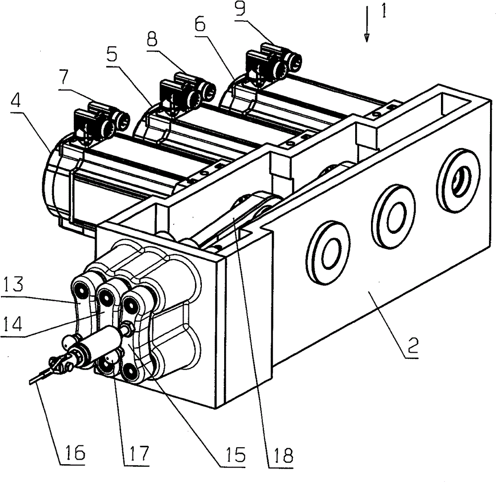
[0023] figure 1 A jacquard device 1 of a warp knitting machine is shown schematically with a housing 2 and three drive motors 4 , 5 , 6 . The drive motor is designed as a so-called "brushless DC motor", ie as a permanently excited synchronous machine, which is actuated via the control interfaces 7 , 8 , 9 . The motors 4, 5, 6 can rotate in two rotational directions. The drive shafts 10 , 11 , 12 can be controlled with high precision in such a way that they assume a defined angular position.

[0024] Each motor acts on a coupling element 13, 14, 15, which is reciprocable in a deflection direction, ie in the longitudinal extension of the thread guide bar not described in detail. A strand 16 is fastened to the coupling element 15 , which establishes a connection to a thread guide bar not described in detail. Corresponding twisted wires (or other connecting elements) can also be fastened to other connecting elements 13 , 14 . Each linking element 13, 14, 15 also has a fixing p...


PUM


Abstract

A knitting machine provided with at least one first drive shaft assembly (10, 28, 29) and a second drive shaft arrangement (11, 30, 31), said first drive shaft assembly (10, 28, 29) and the second drive shaft arrangement (11, 30, 31) running parallel axes (21, 22) have, the first drive shaft arrangement (10, 28, 29) having at least a first connecting rod (18) having a first connecting rod end, is connected, and the second drive shaft arrangement (11, 30, 31) is connected to at least one second connecting rod (19) having a second connecting rod eye. Great freedom in the design is expected of the knitting machine. For this purpose, it is provided that the at least one second connecting rod (19) has a recess which is passed through the first drive shaft arrangement (10, 28, 29).

Description

technical field [0001] The invention relates to a knitting machine with at least one first drive shaft assembly (Antriebswellenanordnung) and a second drive shaft assembly, wherein the first drive shaft assembly and the second drive shaft assembly have axes extending in parallel, the first drive shaft assembly The shaft assembly is coupled with at least one first link (having a first link bore) and the second drive shaft assembly is coupled with at least one second link (having a second link bore). Background technique [0002] A knitting machine of this type is known, for example, from document EP1013812B1. [0003] The invention will be described below using the example of the control of the guide bar in a warp knitting machine. However, the present invention is not limited to this embodiment. [0004] In a warp knitting machine, the thread guide bar is controlled in an offset direction, that is to say in the direction of its longitudinal extension, depending on the desi...

Claims


Application Information

Patent Timeline
IPC IPC(8): D04B27/32D04B27/26
CPCD04B27/26
Inventor S.胡斯G.克劳斯
Owner KARL MAYER STOLL R&D GMBH
Why Eureka
Try Eureka