Double clutch transmission

A dual clutch, transmission technology, applied in the direction of vehicle gearbox, transmission, transportation and packaging, etc., to achieve the effect of high output torque or driving power

Inactive Publication Date: 2010-10-20
ZF FRIEDRICHSHAFEN AG
View PDF7 Cites 2 Cited by
  • Summary
  • Abstract
  • Description
  • Claims
  • Application Information

AI Technical Summary

Problems solved by technology

Another disadvantage is obtained in this known power shift transmission in that only power shifting between the first gear and the second gear is possible

Method used


Image

  • Double clutch transmission
  • Double clutch transmission
  • Double clutch transmission

Examples


Embodiment Construction

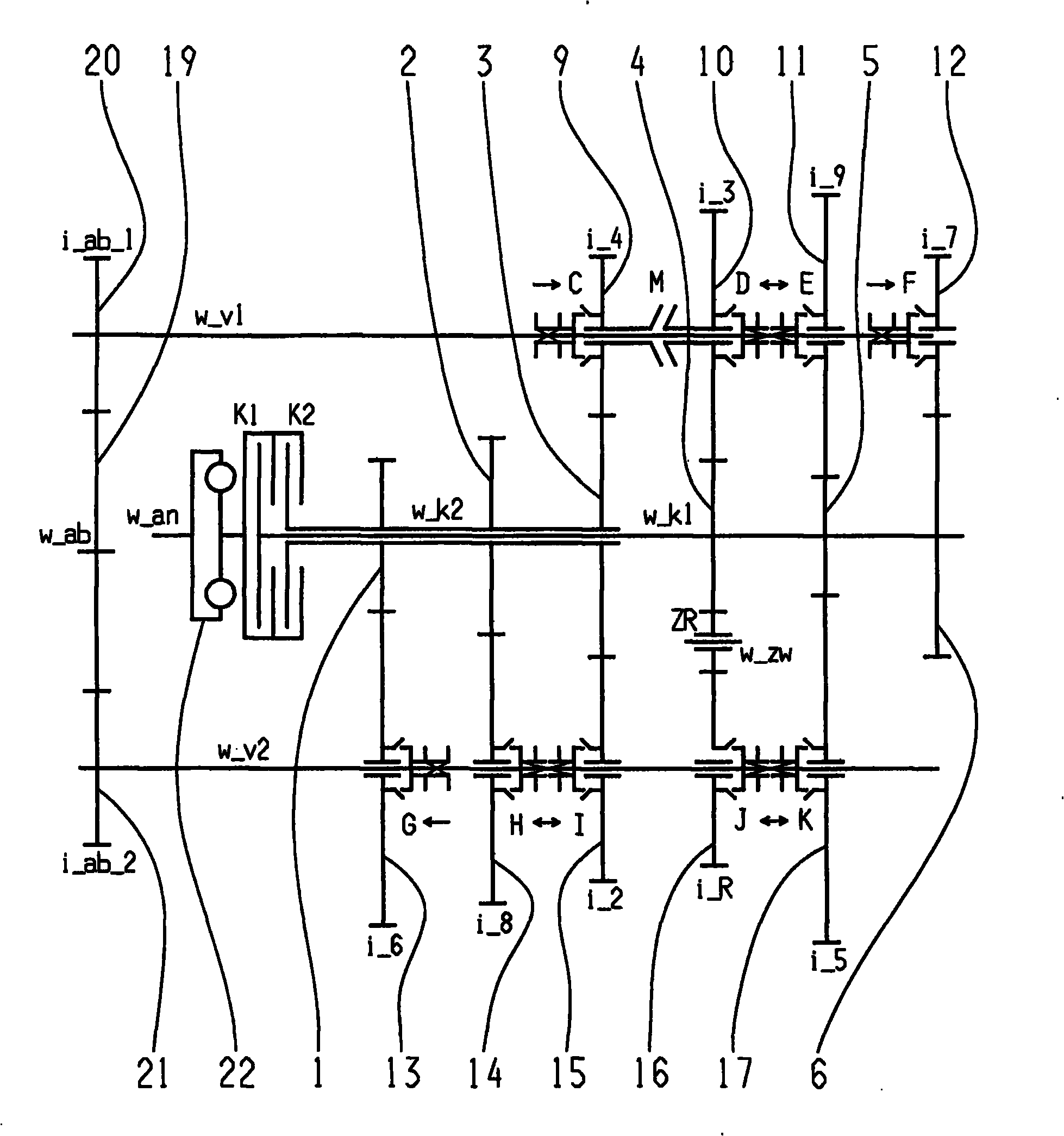
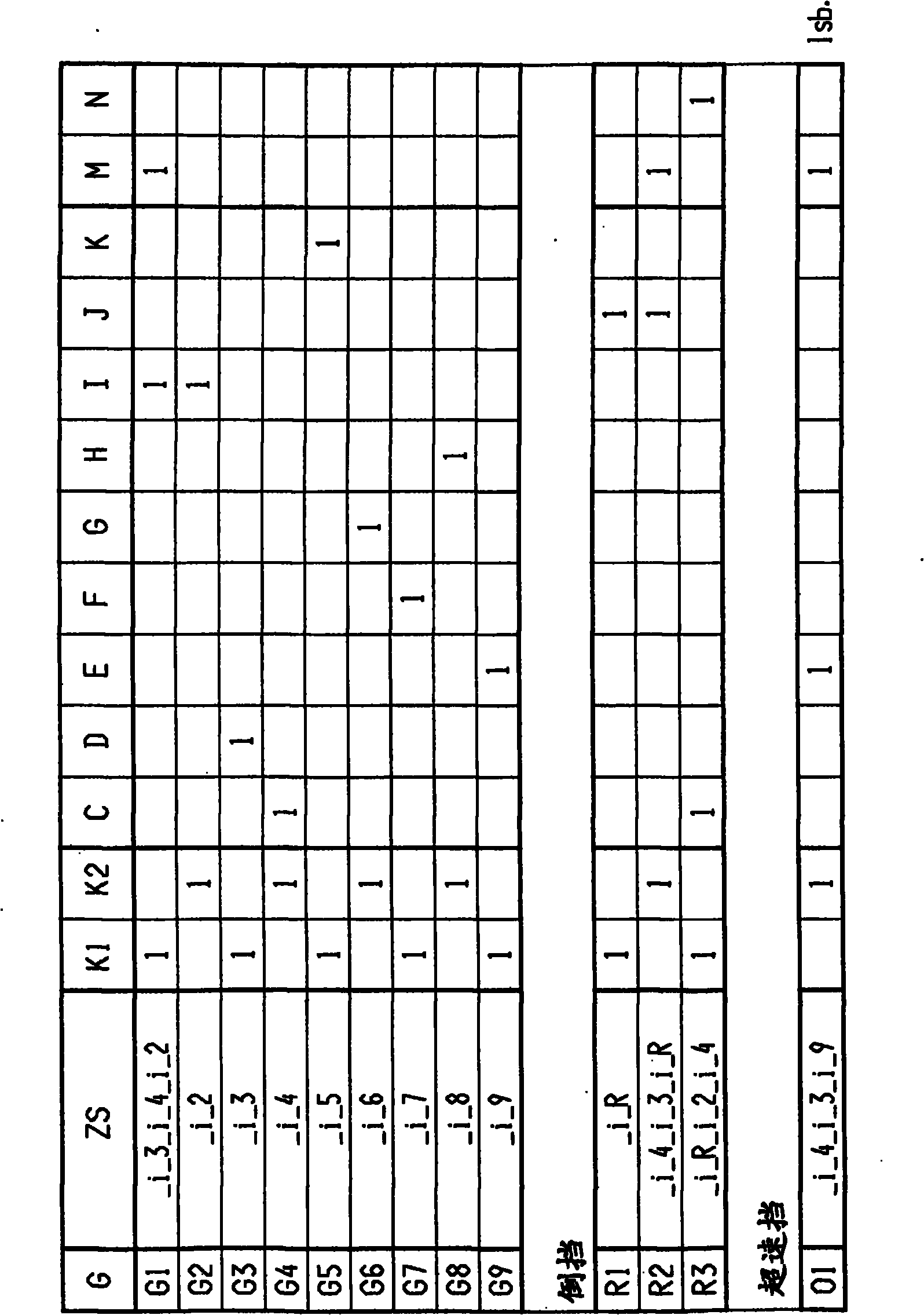
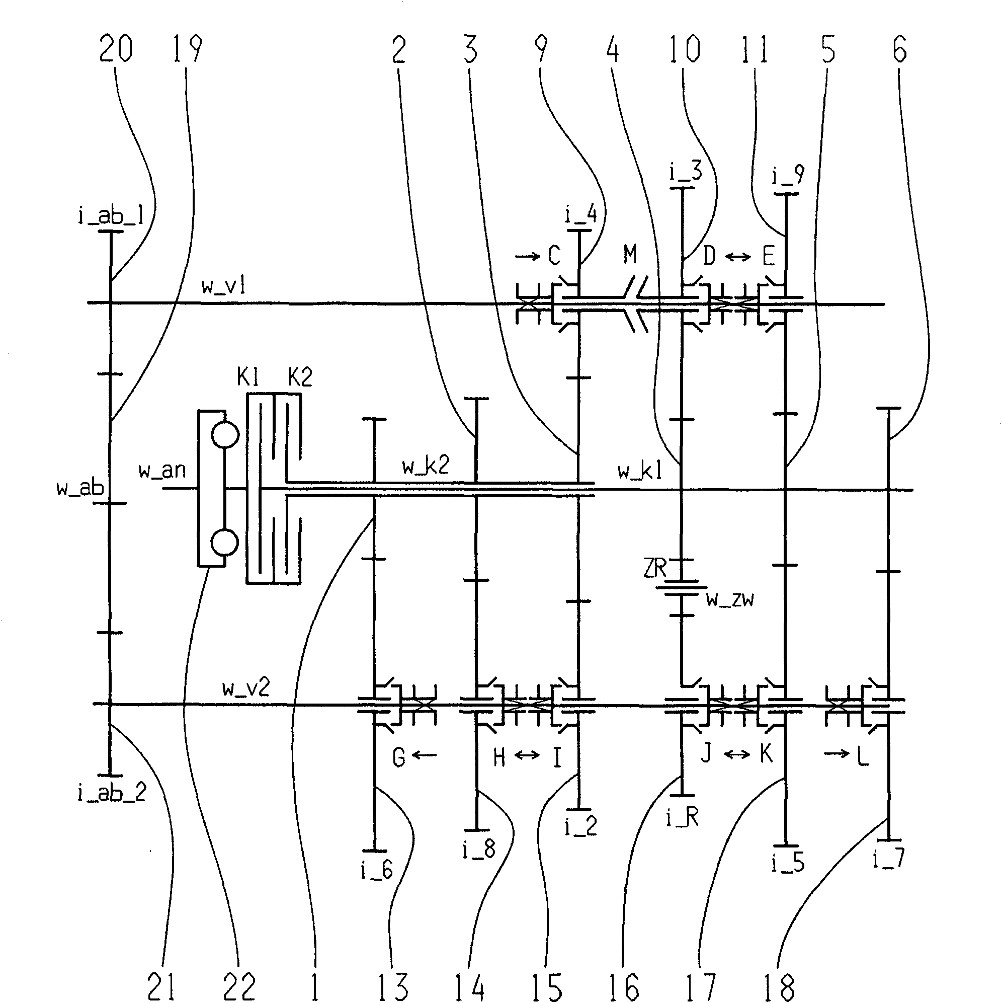
[0057] exist figure 1 , 3 , 5, 7, 9, 11, 13, 15, 17, 19, 21 and 23 respectively show a possible implementation of a nine-speed dual-clutch transmission. The respective shift diagrams for the different implementations are in figure 2 , 4 , 6, 8, 10, 12, 14, 16, 18, 20, 22, and 24 are shown in tabular form.

[0058] The nine-speed dual-clutch transmission includes two clutches K1 , K2 , whose input side is connected to a drive shaft w_an and whose output side is each connected to one of two transmission input shafts w_k1 , w_k2 arranged coaxially with one another. Furthermore, a torsional vibration damper 22 can be arranged on the drive shaft w_an. In addition, two intermediate shafts w_v1, w_v2 are provided, and gear gears formed as idler gears 7, 8, 9, 10, 11, 12, 13, 14, 15, 16, 17, 18 are rotatably supported in the intermediate on axis. On the two transmission input shafts w_k1, w_k2 there are shift gears arranged in a rotationally fixed manner and designed as fixed g...


PUM


Abstract

A double clutch transmission comprising two clutches which each have input sides connected to a drive shaft and output sides respectively connected to one of two transmission input shafts coaxial arranged with respect to one another. At least two countershafts having toothed idler gearwheels pivotally supported thereon while toothed fixed gearwheels are disposed on the transmission input shafts and which engage with at least some of the idler gearwheels. A plurality of coupling devices are provided for coupling an idler gearwheel to the respective countershaft in a rotationally fixed manner. An output gearwheel, on each respective countershaft, is coupled to gearing of an output shaft. At least one shift element is provided for connecting two toothed gearwheels in a rotationally fixed manner such that a plurality of power shifting forward gears and at least one reverse gear can be shifted.

Description

technical field [0001] The invention relates to a dual clutch transmission of the type specified in the preamble of claim 1 . Background technique [0002] A six-speed or seven-speed dual clutch transmission is known from DE 10305241 A1. The dual-clutch transmission comprises two clutches which are each connected with their input sides to a drive shaft and with their output sides to each of two transmission input shafts. The two transmission input shafts are arranged coaxially with each other. The other two countershafts are arranged with axes parallel to the two transmission input shafts, and the idler gears of the two countershafts mesh with the fixed gears of the transmission input shafts. In addition, the coupling device is fastened in an axially displaceable, rotationally fixed manner on the layshaft in order to be able to engage the corresponding gearwheel. The correspondingly selected transmission ratio is transmitted to the differential via the output gear. In or...

Claims


Application Information

Patent Timeline
Patent Type & Authority Applications(China)
IPC IPC(8): F16H3/12
CPCF16H2003/0931F16H2003/0826F16H2200/0091F16H2200/0026F16H3/006F16H2200/0086F16H2200/006F16H2200/0065F16H2200/0095Y10T74/19233
Inventor W·里格尔P·雷克G·贡波尔茨贝格
Owner ZF FRIEDRICHSHAFEN AG
Why Eureka
Try Eureka