
Rotatable distributed radar life detection and positioning equipment

A life detection and distributed technology, which is applied in measuring devices, radio wave measurement systems, radio wave reflection/re-radiation, etc., can solve problems such as inability to carry out large baselines, detection, and slow search speed, and achieve improved detection performance and Practicality, improvement of data transmission quality, effect of increased degree of freedom

Pending Publication Date: 2020-07-10
湖南正申科技有限公司
View PDF0 Cites 3 Cited by
  • Summary
  • Abstract
  • Description
  • Claims
  • Application Information

AI Technical Summary

Problems solved by technology

[0005] (1) Monostatic radar search is slow and positioning accuracy is poor;
[0006] Because the single-base radar can only detect a small-scale area near the location, it cannot detect in a large area at the same time, and the search speed is slow; the baseline of the single-base radar is limited by the outer box of the package, and it cannot perform large-scale baseline detection, and the angular resolution is poor, which eventually leads to Inaccurate targeting
[0007] (2) The situation of detection omission is serious;
The polarization direction of the existing radar is fixed, and targets inconsistent with the polarization direction of the radar will be missed in actual detection
[0009] (3) The wireless distributed radar is severely interfered;
However, in the complex environment of the disaster site, various personnel and equipment will seriously interfere with the radar wireless transmission channel, resulting in discontinuous data transmission and even equipment interruption; in addition, radar relies on transmitters to emit electromagnetic signals for detection, while WIFI wireless transmission data also uses electromagnetic waves In space transmission, this technology itself will also affect radar detection
Wireless networking devices will not work in places with weak GPS signals such as jungles and valleys
Therefore, the program is not very practical

Method used


Image

  • Rotatable distributed radar life detection and positioning equipment
  • Rotatable distributed radar life detection and positioning equipment
  • Rotatable distributed radar life detection and positioning equipment

Examples


Embodiment Construction

[0035] The present invention will be further described in detail below in conjunction with the accompanying drawings and specific embodiments.

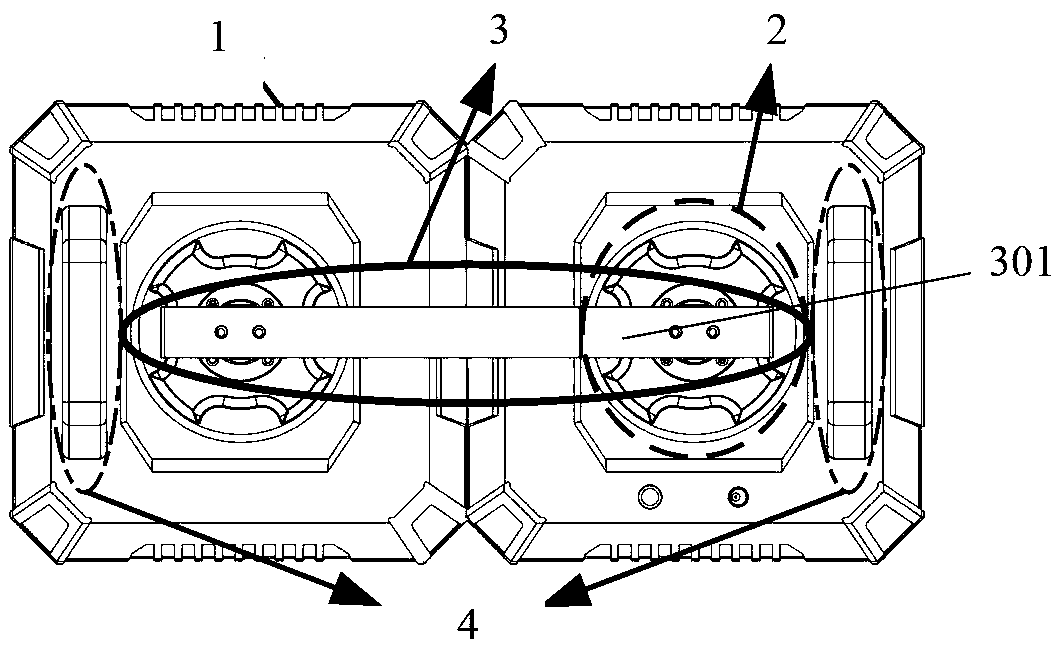
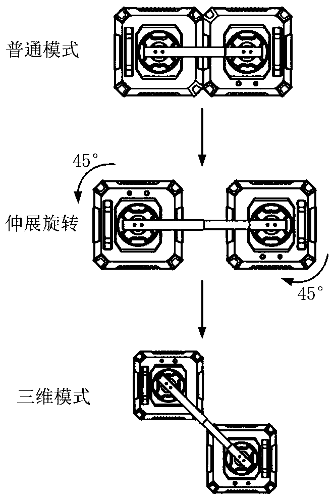
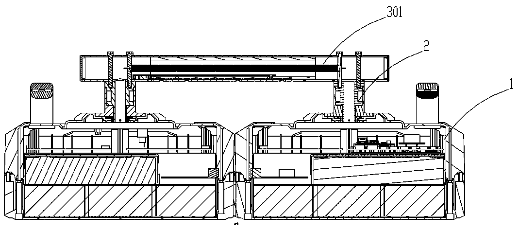
[0036] Such as figure 1 and Figure 4 As shown, the rotatable distributed radar life detection and positioning equipment of the present invention includes more than two radar units 1, and each radar unit 1 is provided with a rotating mechanism 2, through which the individual radar units can be 1 Rotate around a fixed axis to adjust the direction of antenna polarization. The radar life detection and positioning equipment is provided with a handle 4 for easy operation.

[0037] Such as figure 1 In the above, taking two independent radar units 1 as an example, the two square boxes on the left and right are independent radar units 1, and each radar unit 1 contains one transmission and two reception channels, and each radar unit 1 can transmit signals and receive signals Features. The data wires and signal wires are assembled in the t...


PUM


Abstract

The invention discloses rotatable distributed radar life detection and positioning equipment which comprises more than two independent radar units, each radar unit is provided with a rotating mechanism, and the independent radar units are enabled to rotate around a fixed shaft through the rotating mechanisms so as to adjust the polarization direction of an antenna. The equipment has the advantagesof simple structure, simple operation, wide application range, capability of realizing large-range quick search and full-polarization target detection and the like.

Description

technical field [0001] The invention mainly relates to the technical field of radar life detection equipment, in particular to a rotatable distributed radar life detection and positioning equipment. Background technique [0002] Radar life detection and positioning equipment is mainly used to detect survivors buried in ruins after earthquakes, landslides and other disasters. The general environment of the disaster site is harsh: mud, building ruins, steel bars and metal are all over the place; rescue site personnel and equipment are mixed, and all kinds of interference are serious. Most of the existing radar life equipment is single-base radar (that is, radar transmitters, receivers and other components are all packaged together as a complete device). Large-scale packaging, so the radar baseline is short, the angular resolution is poor, and it is difficult to perform multi-target detection. Secondly, after a disaster occurs, the affected area is generally large. Single-bas...

Claims


Application Information

Patent Timeline
Patent Type & Authority Applications(China)
IPC IPC(8): G01S13/88G01S13/06G01S7/02
CPCG01S7/02G01S13/06G01S13/887
Inventor 金养昊周伟袁雪林张旺新
Owner 湖南正申科技有限公司
Learn More