Automotive power compensation clutch and clutch method

A power compensation and magnetic powder clutch technology, applied in clutches, fluid clutches, transmissions, etc., can solve the problems of poor anti-slip performance, difficult control, high manufacturing cost, etc., and achieve strong anti-slip performance, simple mechanism structure, The effect of low manufacturing cost

Inactive Publication Date: 2016-03-02
HUNAN SINO GERMAN AUTOMATIC TRANSMISSION
View PDF6 Cites 1 Cited by
  • Summary
  • Abstract
  • Description
  • Claims
  • Application Information

AI Technical Summary

Problems solved by technology

[0010] What the patent of the present invention aims to solve is to propose a new design scheme of a vehicle power compensation clutch with a new working principle to solve the problems of high manufacturing cost, difficult control and poor anti-slip performance of the traditional dual clutch for vehicles

Method used


Image

  • Automotive power compensation clutch and clutch method
  • Automotive power compensation clutch and clutch method

Examples


Embodiment Construction

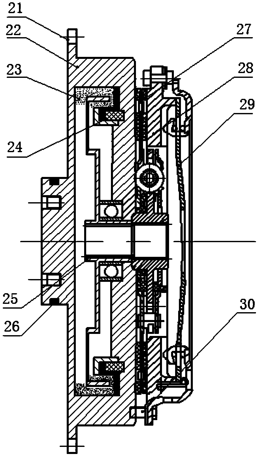
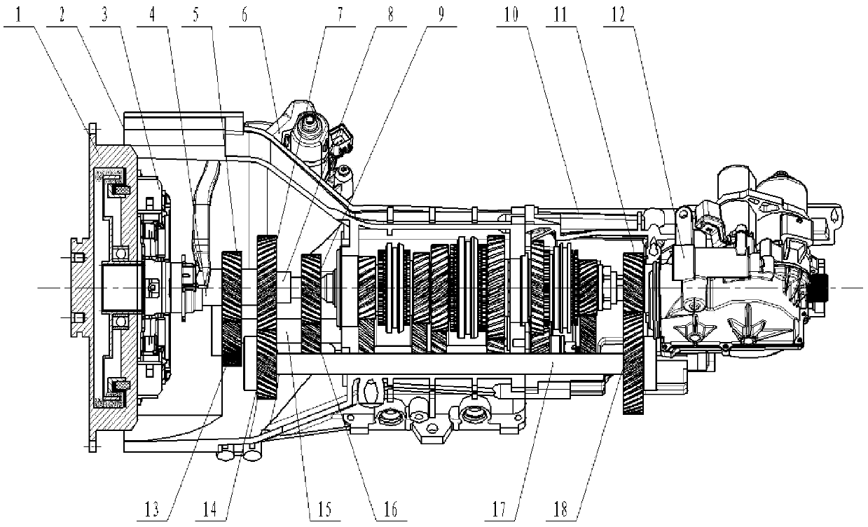
[0023] see figure 1 The clutch of the present invention includes a magnetic powder clutch and a dry clutch, the magnetic powder clutch includes a magnetic powder clutch starting gear, a magnetic powder clutch active part, magnetic powder, a magnetic powder clutch excitation coil, a magnetic powder clutch follower and a magnetic powder clutch power supply slip ring, and the magnetic powder clutch starting gear is embedded in magnetic powder The active part of the clutch and the driven part of the magnetic powder clutch are connected to the active part of the magnetic powder clutch through bearings. The cavity between the active part of the magnetic powder clutch and the driven part of the magnetic powder clutch stores magnetic powder. The excitation coil of the magnetic powder clutch is fixed on the inner wall of the active part of the magnetic powder clutch to supply power. The slip ring is squeezed and connected to the active part of the magnetic powder clutch through interfer...


PUM


Abstract

The invention discloses an automotive power compensation clutch and a clutch method. The power compensation clutch is formed by combining a magnetic powder clutch and a dry clutch. A magnetic powder chain is formed by magnetic powder under excitation current, the principle of transmitting torque by cutting the magnetic powder chain is combined with the working principle of the dry clutch, and therefore double clutches of a traditional automotive wet type friction plate structure are replaced. Torque transmission of the magnetic powder clutch is completed through the effect of shearing the magnetic powder chain under the electromagnetic effect, and therefore power compensation is achieved. The working principle of the dry clutch is used for switching the working state and the non-working state of the clutch. Linear growth and linear reduction of magnetizing current of a magnetic powder sub-clutch are used for completing torque transmission of the magnetic powder clutch and the switching process of the working state of the dry clutch. Compared with traditional wet and dry double clutches, the automotive powder compensation clutch is high in responding speed, free of impacts, noise and pollution, longer in sliding and friction resisting time and capable of achieving controlling more easily.

Description

technical field [0001] The patent of the invention belongs to the technical field of automatic transmission of vehicles, and in particular relates to a power compensation clutch and a clutch method for a vehicle combining a magnetic powder clutch and a dry clutch. Background technique [0002] The earliest research on dual-clutch transmission (DCT) began in 1938. The first mass-produced dual-clutch transmission product was the DQ250 product of German Volkswagen. Dual-clutch transmission has become the target favored by major domestic and foreign OEMs and transmission suppliers. The function realization of the dual clutch transmission is based on the dual clutch, so the dual clutch becomes the key component in the research of the dual clutch transmission. [0003] At present, the dual clutch includes two forms, one is the dual clutch with wet friction plate represented by Borgwarner and the dual clutch with dry friction plate represented by LUK. [0004] Whether it is a wet ...

Claims


Application Information

Patent Timeline
Patent Type & Authority Applications(China)
IPC IPC(8): F16D37/02F16H3/08
Inventor 魏英俊
Owner HUNAN SINO GERMAN AUTOMATIC TRANSMISSION
Why Eureka
Try Eureka