
Heat exchange assembly, heat exchanger and refrigerating system

A technology of heat exchange components and heat exchangers, which is applied in the field of heat exchangers, refrigeration systems, and heat exchange components. It can solve problems such as low heat exchange efficiency, gaps, and difficult processing, so as to improve heat exchange efficiency and strengthen Compression capacity, the effect of improving the service life

Active Publication Date: 2016-03-02
GREE ELECTRIC APPLIANCES INC OF ZHUHAI
View PDF6 Cites 7 Cited by
  • Summary
  • Abstract
  • Description
  • Claims
  • Application Information

AI Technical Summary

Problems solved by technology

[0003] For example, the patent number is CN200580049152.X, and the name is a flat tube single serpentine carbon dioxide heat exchanger. The flat tube heat exchanger has a roughly serpentine structure; Realize heat exchange between coolant and refrigerant
[0004] The patent number is CN200920300198.X, and the name is a corrugated tube with a small metal tube around it, which can realize the heat exchange between the cooling liquid and the refrigerant; but the small metal tube needs to be wound on a longer corrugated tube, which requires special equipment and is difficult to process; the small tube There is a gap between the metal tube and the heat transfer efficiency is low

Method used


Image

  • Heat exchange assembly, heat exchanger and refrigerating system
  • Heat exchange assembly, heat exchanger and refrigerating system
  • Heat exchange assembly, heat exchanger and refrigerating system

Examples


Embodiment Construction

[0025] The present invention will be described in detail below with reference to the accompanying drawings and examples.

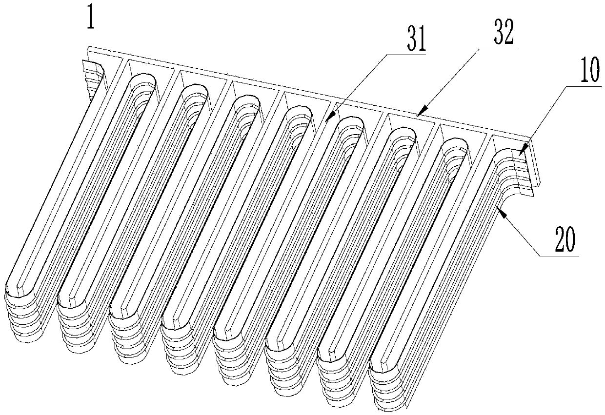
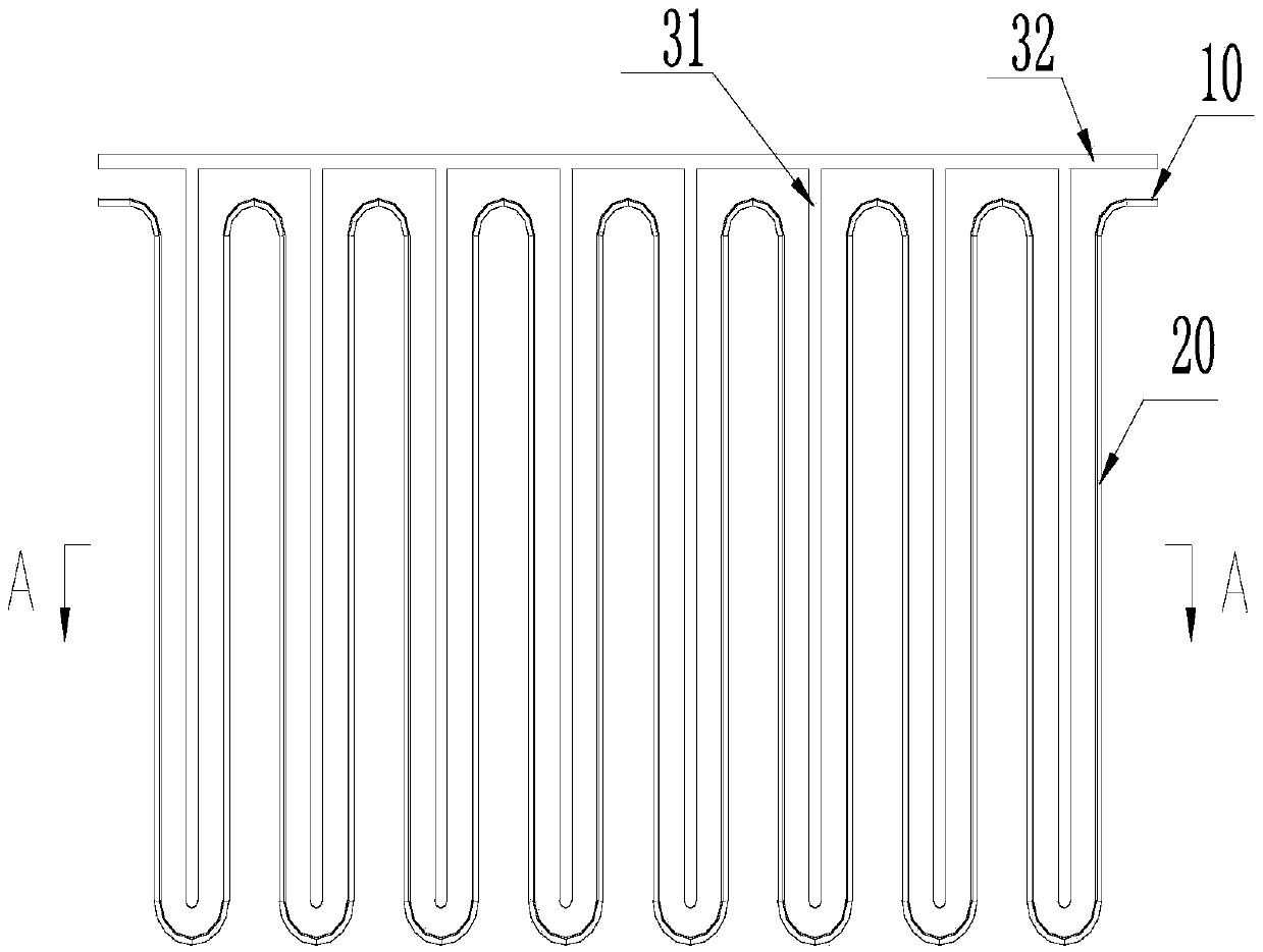
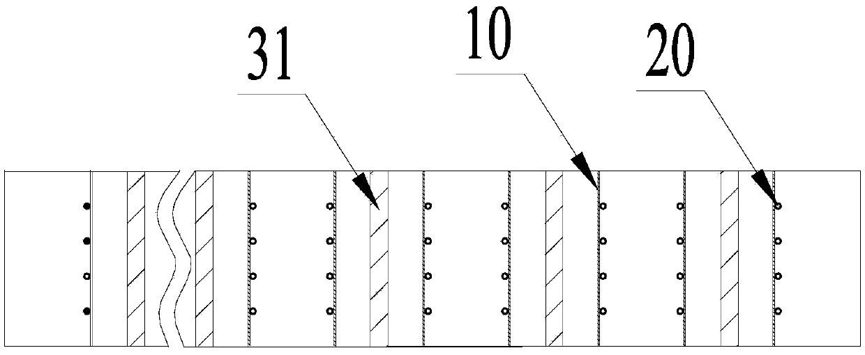
[0026] Such as figure 1 As shown, the heat exchange assembly 1 according to the present invention includes a heat conduction plate 10 , a refrigerant pipe 20 attached to the first side of the heat conduction plate 10 , and a separator for cooling liquid forming a serpentine shape with the second side of the heat conduction plate 10 . By arranging the refrigerant and the cooling liquid on both sides of the heat conduction plate 10, the refrigerant and the cooling liquid are separated, preventing the refrigerant pipe 20 from being corroded by the cooling liquid, and improving the service life of the heat exchange component 1; at the same time, the refrigerant pipe 20 is attached to the snake On the heat conducting plate 10, the serpentine cooling liquid path formed by the partition plate and the heat conducting plate 10 makes the heat exchange distance betwe...


PUM


Abstract

The invention provides a heat exchange assembly, a heat exchanger and a refrigerating system. The heat exchange assembly comprises a heat transfer plate, multiple refrigerant pipes and a partition plate. The heat transfer plate is in a snake shape to form multiple U-shaped structures. The refrigerant pipes are attached to the first sides of the heat transfer plate and allow a refrigerant to circulate inside. The partition plate comprises multiple spacing plates inserted into the U-shaped structures of the second sides of the heat transfer plate and fixing plates for fixing the spacing plates. The second sides of the heat transfer plate form a snake-shaped cooling liquid way through the spacing plates and the fixing plates. According to the heat exchange assembly, the heat exchanger and the refrigerating system, the refrigerant pipes allowing the refrigerant to circulate are arranged on the first sides of the heat transfer plate, and the cooling liquid way is arranged on the second sides of the heat transfer plate, so that the refrigerant is separated from cooling liquid, the refrigerant pipes are prevented from being corroded by the cooling liquid, and the service life of the heat exchange assembly is prolonged; meanwhile, the refrigerant pipes are attached to the snake-shaped heat transfer plate, and the heat exchange distance of the refrigerant in the heat exchanger and the cooling liquid way is extended as long as possible through the snake-shaped cooling liquid way formed by the partition plate and the heat transfer plate, so that heat exchange efficiency is improved, and the pressure bearing capacity of the heat exchanger is enhanced.

Description

technical field [0001] The invention relates to the field of refrigeration systems, in particular to a heat exchange component, a heat exchanger and a refrigeration system. Background technique [0002] At present, the refrigeration system includes a compressor and a heat exchanger, and the heat exchanger is related to the heat exchange efficiency. In the prior art, there are various structures of heat exchangers. [0003] For example, the patent number is CN200580049152.X, and the name is a flat tube single serpentine carbon dioxide heat exchanger. The flat tube heat exchanger has a roughly serpentine structure; Realize heat exchange between coolant and refrigerant. [0004] The patent number is CN200920300198.X, and the name is a corrugated tube with a small metal tube around it, which can realize the heat exchange between the cooling liquid and the refrigerant; but the small metal tube needs to be wound on a longer corrugated tube, which requires special equipment and i...

Claims


Application Information

Patent Timeline
IPC IPC(8): F28F9/22F25B41/06F25B47/00F25B41/37
Inventor 黄昌成林海佳吴永和牛永健
Owner GREE ELECTRIC APPLIANCES INC OF ZHUHAI
Features
  • Generate Ideas
  • Intellectual Property
  • Life Sciences
  • Materials
  • Tech Scout
  • Unparalleled Data Quality
  • Higher Quality Content
  • 60% Fewer Hallucinations
Learn More