Dust removing method for tube-type heat exchanger and dust removing device for tube-type heat exchanger

The technology of a tubular heat exchanger and an ash cleaning device is applied in the field of metallurgy, which can solve the problems of reducing the heat exchange efficiency of the tubular heat exchanger, and achieve the effect of reducing the thickness and ensuring the heat exchange efficiency.

Inactive Publication Date: 2016-03-02
SHANDONG IRON & STEEL CO LTD
View PDF12 Cites 6 Cited by
  • Summary
  • Abstract
  • Description
  • Claims
  • Application Information

AI Technical Summary

Problems solved by technology

[0002] The tubular heat exchanger uses the wall of the tube bundle enclosed in the shell as the heat transfer surface of the partition wall heat exchanger. During the heat exchange process of the high-temperature exhaust gas, the exhaust gas often carries a certain amount of dust. And some compounds that exist in gaseous form. During the cooling process of exhaust gas, chemical reactions occur between the compounds in gaseous form in exhaust gas to form liquid compounds with strong adhesion or solid compounds with strong adhesion. Or the gaseous compounds in the exhaust gas are directly condensed to form liquid compounds with strong adhesion or solid compounds with strong adhesion. During the process of gas circulation, the liquid compounds or solid compounds with strong adhesion will Carrying dust and adsorbing on the wall of the tube heat exchanger together, causing the heat exchange efficiency of the tube heat exchanger to decrease, and in serious cases, it needs to be shut down for cleaning

Method used


Image

  • Dust removing method for tube-type heat exchanger and dust removing device for tube-type heat exchanger
  • Dust removing method for tube-type heat exchanger and dust removing device for tube-type heat exchanger

Examples


Embodiment 1

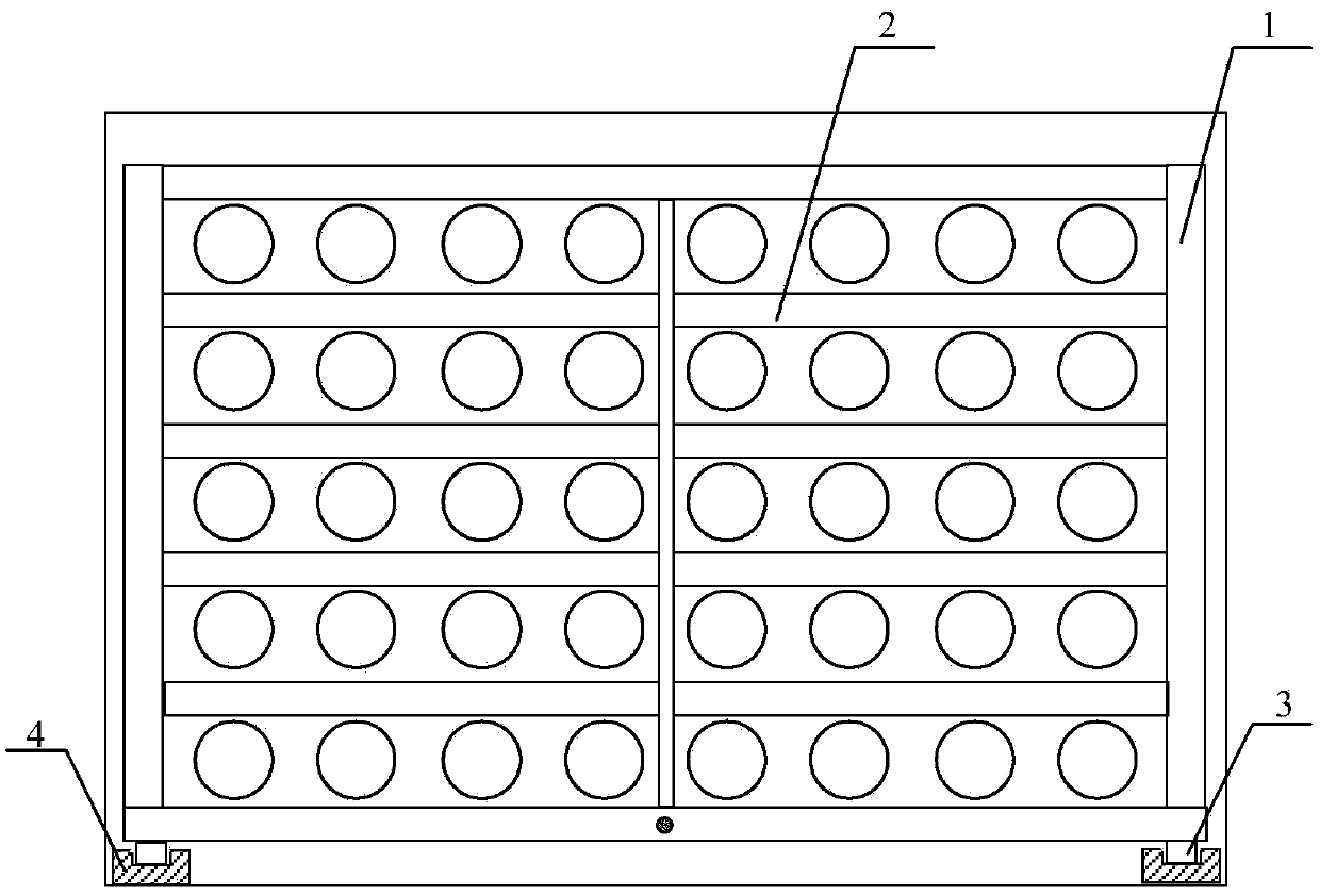
[0054] Embodiment 1, the cleaning knife 2 includes a mounting plate and a knife head fixedly connected to the mounting plate. ;

Embodiment 2

[0055] Embodiment 2, the cleaning knife 2 includes a mounting plate and a cutter head fixedly connected with the mounting plate, the cutter head is a circular cutter head, and the mounting plate is connected with the vertical plate;

Embodiment 3

[0056] Embodiment 3, the cleaning knife 2 is a rectangular plate, and the length of the rectangular plate is equal to the width of the tubular heat exchanger.

[0057] The dust-cleaning knife 2 in Embodiment 1 and Embodiment 3 can only scrape one side of the heat exchange tube during a single scraping process, and the dust-cleaning knife 2 in Embodiment 2 can It is possible to scrape the entire circumference of the heat exchange tube.

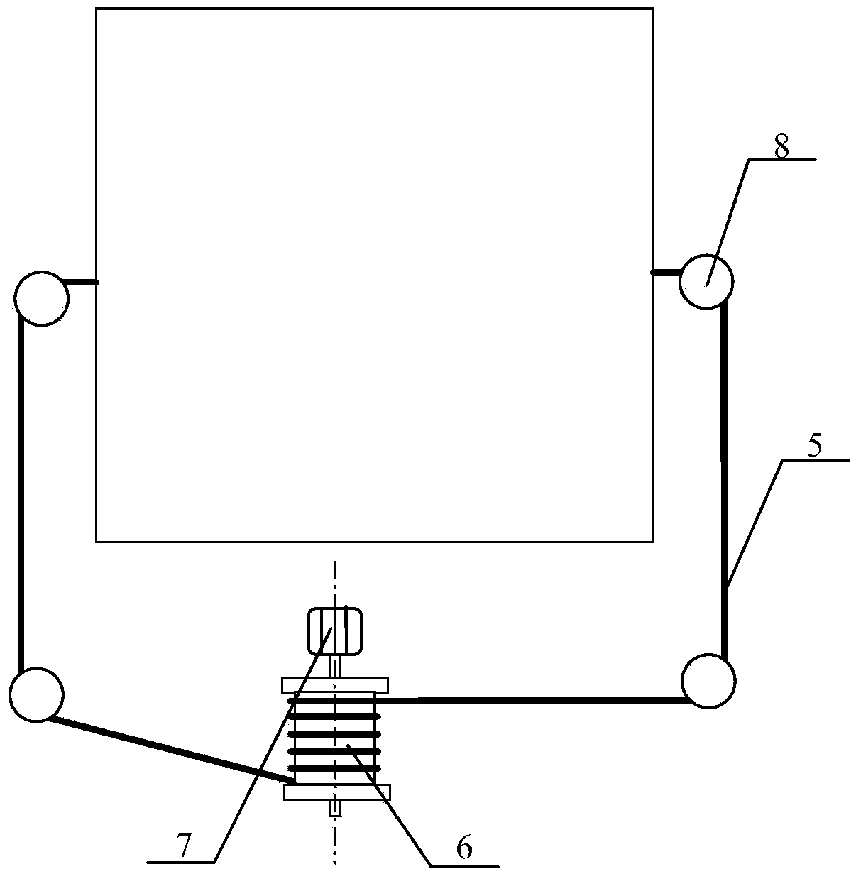
[0058] In order to ensure the stable connection of the guide rail 3, preferably, the guide rail 3 is connected to the bottom plate of the tube heat exchanger, and the installation of the dust cleaning device of the tube heat exchanger can be realized without the help of other devices, thereby reducing the cost of the tube heat exchanger. The cost and volume of the cleaning device. In order to facilitate the connection between the tube heat exchanger dust removal device and the bottom plate, preferably, the tube heat exchanger and the bottom pl...


PUM


Abstract

The invention discloses a dust removing method for a tube-type heat exchanger and a dust removing device thereof. The dust removing device comprises a cutter frame, dust removing cutters, first sliding wheels and guiding rails. The dust removing cutters are installed on the cutter frame and can scrape dust on heat exchange tubes. The arranging direction of the dust removing cutters is perpendicular to the axial direction of the heat exchange tubes, and the width of each dust removing cutter is smaller than the distance between the two adjacent rows of the heat exchange tubes, so it is ensured that the dust removing cutters can move back and forth between the two adjacent rows of the heat exchange tubes. In the specific using process, the cutter frame is pushed to slide in the guiding rails through the first sliding wheels, and the dust on the heat exchange tubes is scraped through the dust removing cutters along with the motion of the cutter frame, so that the dust on the heat exchange tubes is removed in a large area, the thickness of the dust covering the heat exchange tubes is reduced, and the heat exchanging efficiency of the heat exchange tubes is ensured.

Description

technical field [0001] The invention relates to the technical field of metallurgy, in particular to a method for cleaning a tube heat exchanger and a device for cleaning a tube heat exchanger. Background technique [0002] The tubular heat exchanger uses the wall of the tube bundle enclosed in the shell as the heat transfer surface of the partition wall heat exchanger. During the heat exchange process of the high-temperature exhaust gas, the exhaust gas often carries a certain amount of dust. And some compounds that exist in gaseous form. During the cooling process of exhaust gas, chemical reactions occur between the compounds in gaseous form in exhaust gas to form liquid compounds with strong adhesion or solid compounds with strong adhesion. Or the gaseous compounds in the exhaust gas are directly condensed to form liquid compounds with strong adhesion or solid compounds with strong adhesion. During the process of gas circulation, the liquid compounds or solid compounds wit...

Claims


Application Information

Patent Timeline
Patent Type & Authority Applications(China)
IPC IPC(8): F28G1/08
CPCF28G1/08
Inventor 刘元意曾晖刘运东李建云
Owner SHANDONG IRON & STEEL CO LTD
Why Eureka
Try Eureka