Zero-sequence current detection device and method for neutral point grounding system through small resistance
A technology of small resistance grounding and zero-sequence current, applied in the field of power system, can solve the problem of low sensitivity of differential protection action, achieve the effect of improving sensitivity, increasing sensitivity, and reducing starting current value
- Summary
- Abstract
- Description
- Claims
- Application Information
AI Technical Summary
Problems solved by technology
Method used
Image
Examples
Embodiment 1
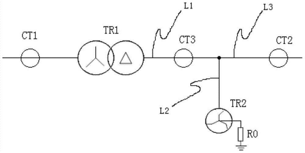
[0033] Such as figure 2 As shown, the neutral point grounding system through a small resistance includes the main transformer TR1, the grounding transformer TR2 and the resistor R0, the secondary side output line of the main transformer TR1 includes the main trunk line and at least two branch lines, and the secondary side includes the Δ side and the Y side ,For example, figure 2 The Δ-side output line of the secondary side of the main transformer TR1 includes a main line L1 and at least two branch lines L2 and L3. The high voltage side of the grounding transformer TR2 is connected to the first branch line L2, the low voltage side of the grounding transformer TR2 is connected to one end of the resistor R0, and the other end of the resistor R0 is grounded.
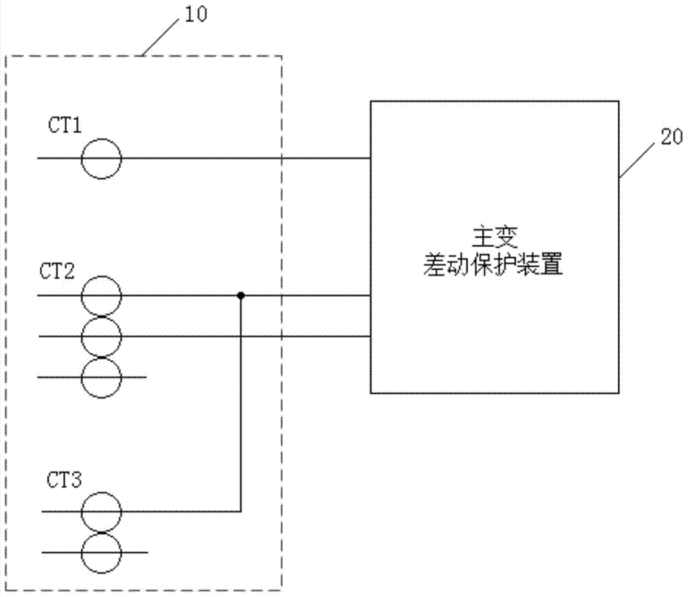
[0034] This embodiment provides a zero-sequence current detection device for a neutral point grounded system through a small resistance, such as figure 2 The shown neutral point is grounded by a small resistance, such a...
Embodiment 2
[0043] This embodiment provides a zero-sequence current detection method for a neutral point grounded system through a small resistance, for example, it is applied to the zero-sequence current detection device in the above-mentioned embodiment 1, such as Figure 5 As shown, the zero-sequence current detection method includes the following steps:
[0044] S1. Configure the primary side of the first current transformer CT1 on the primary side input wire of the main transformer TR1, configure the primary side of the second current transformer CT2 on the second branch line L3 of the main transformer TR1, and configure the primary side of the second current transformer CT2 on the main transformer TR1 The primary side of the third current transformer CT3 is arranged on the trunk line L1;
[0045] S2. Connect the secondary side of the first current transformer CT1 to the first current input end of the main transformer differential protection device 20;
[0046] S3, connecting the fi...
PUM
 Abstract
Description
Claims
Application Information
 - R&D
- Intellectual Property
- Life Sciences
- Materials
- Tech Scout
- Unparalleled Data Quality
- Higher Quality Content
- 60% Fewer Hallucinations
Browse by: Latest US Patents, China's latest patents, Technical Efficacy Thesaurus, Application Domain, Technology Topic, Popular Technical Reports.
© 2025 PatSnap. All rights reserved.Legal|Privacy policy|Modern Slavery Act Transparency Statement|Sitemap|About US| Contact US: help@patsnap.com


