Linear reluctance motor, engine and electromotor

A reluctance motor, linear technology, applied in the direction of AC motor control, electric components, electrical components, etc., can solve the problems of high temperature, less winding turns, and small reluctance of the motor

Inactive Publication Date: 2016-03-02
徐夫子 +1
View PDF8 Cites 0 Cited by
  • Summary
  • Abstract
  • Description
  • Claims
  • Application Information

AI Technical Summary

Problems solved by technology

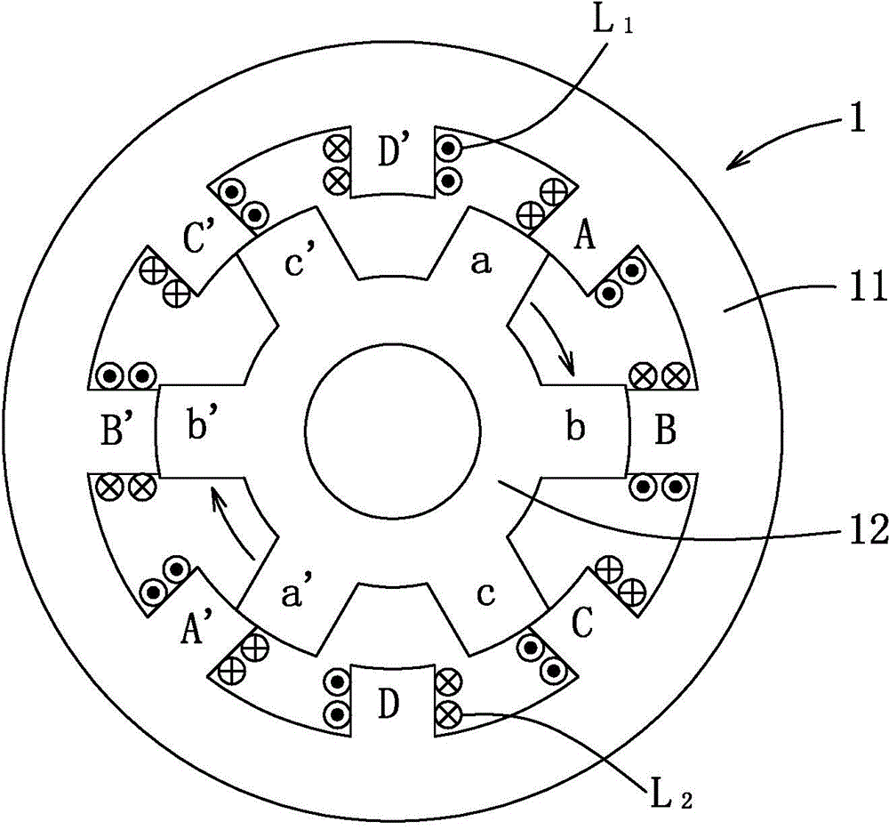
[0003] Existing reluctance motor is to utilize the power operation of rotor 12 and the salient pole of stator 11 to attract each other, but because the number of turns of the winding of each salient pole of stator 11 is few (usually less than 100), the reluctance that produces is little , so it needs to consume a larger current to make each salient pole generate enough magnetic attraction to drive the rotor 12 to run, so the structure of the existing reluctance motor 1 cannot effectively save power
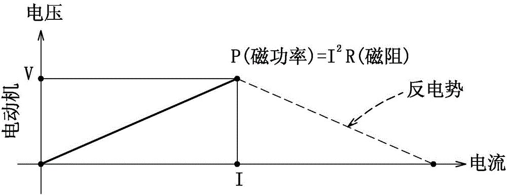
[0004] In addition, if figure 2 As shown, since the magnetic power generated by the existing motor using the reluctance motor 1 is controlled by the current (voltage is fixed), and the winding of the reluctance motor 1 exhibits the characteristic of inductance, the winding will generate counter electromotive force during the degaussing process. (Virtual work, as shown by the dotted line in the figure) generates heat, which makes the motor prone to high temperature
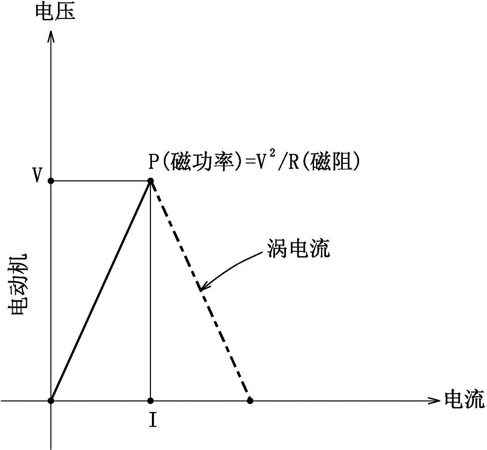
[0005] Furthermore, if image 3 As shown, from the working curve of the existing electromagnet, it can be known that the magnetic power generated by it is controlled by voltage (the current is fixed). virtual work, as shown by the dotted line in the figure) and generate heat

Method used


Image

  • Linear reluctance motor, engine and electromotor
  • Linear reluctance motor, engine and electromotor
  • Linear reluctance motor, engine and electromotor

Examples


Embodiment Construction

[0029] The present invention will be described in detail below in conjunction with the accompanying drawings and embodiments.

[0030] see Figure 4 to Figure 7 As shown, the first embodiment of the linear reluctance engine of the present invention mainly includes a linear reluctance motor 2 and a transmission mechanism 3, and the linear reluctance engine cooperates with a driving circuit 4 to form the linear reluctance motor of the present invention. Such as Figure 5 As shown, the linear reluctance motor 2 mainly includes a solid iron base 21, a non-magnetic sleeve 22 sleeved on the solid iron base 21, and a non-magnetic sleeve 22 wound around the outer surface of the non-magnetic sleeve 22. Exciting coil 23, an iron core 24 passing through the periphery of non-magnetic sleeve 22, a solid iron cover 25 arranged at the other end of non-magnetic sleeve 22, and a The solid iron piston 26.

[0031] Such as Figure 5As shown, a convex portion 211 is formed in the center of th...


PUM


Abstract

A linear reluctance motor, a linear reluctance engine having same, and a linear reluctance electromotor comprising the linear reluctance engine. The linear reluctance motor includes: a solid iron base body, wherein a protruding part is formed on the center of inner surface; a non-magnetically-conductive sleeve with one end sleeving the protruding parton thesolid iron base body; an exciting coil winding the outer surface of the non-magnetically-conductive sleeve; a iron core passing through the periphery of the non-magnetically-conductive sleeve and is separated from the exciting coil, one end surface being pressed against the inner surface of the solid iron base body; a solid iron cover body disposed on the other end of the non-magnetically-conductive sleeve and pressed against the other end surface or the iron core, wherein an opening, which is opposite to and communicated with the non-magnetically-conductive sleeve is formed in the center of the cover body; and a solid iron piston having a first end and a second end being opposite to each other, the first end being accumudated in the sleeve and the second end being stretched out from the opening, herein the solid iron piston can be moved axially relative to the sleeve to moving the second end closely or far away from the opening.

Description

technical field [0001] The present invention relates to a reluctance motor, in particular to a linear reluctance motor, a linear reluctance engine with the linear reluctance motor, and a linear reluctance engine with the linear reluctance engine resistance motor. Background technique [0002] refer to figure 1 , an existing reluctance motor 1 mainly includes a stator 11 and a rotor 12 disposed in the stator 11 . The stator 11 has eight salient poles A, A', B, B', C, C', D, D', and windings L1, L2 respectively wound on the salient poles. And the rotor 12 has six salient poles a, a', b, b', c, c'. Generally, the four-phase windings of the reluctance motor 1 are excited sequentially in a phase-separated excitation method, for example, the salient poles A and A' wound by the A-phase winding generate magnetic force to attract the salient poles a and a' of the rotor 12 towards the stator 11. The salient pole moves in the direction of A and A', such as figure 1 As shown, then ...

Claims


Application Information

Patent Timeline
IPC IPC(8): H02K41/03
CPCH02K7/075H02K33/02H02P25/032
Inventor 徐夫子
Owner 徐夫子
Why Eureka
Try Eureka