

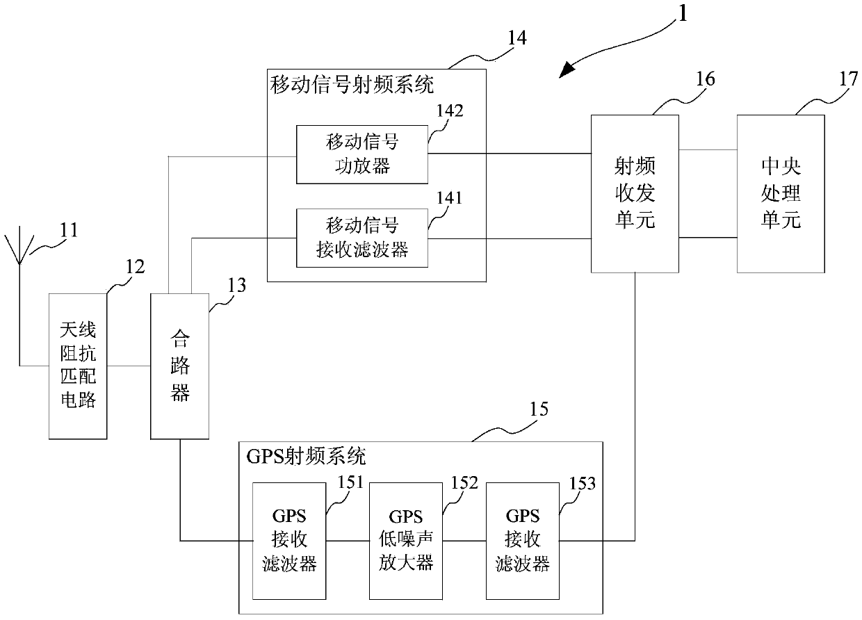
Mobile communication terminal common antenna circuit
A technology for mobile communication terminals and shared antennas, applied to electrical components, transmission systems, etc., can solve the problems of occupying space and a large number of antennas, and achieve the effect of small occupied space and convenient structure and shape design
- Summary
- Abstract
- Description
- Claims
- Application Information
AI Technical Summary
Problems solved by technology
Method used
Image

Examples
Embodiment Construction
[0035] The implementation of the present invention is described below through specific specific examples, and those skilled in the art can easily understand other advantages and effects of the present invention from the content disclosed in this specification. The present invention can also be implemented or applied through other different specific implementation modes, and various modifications or changes can be made to the details in this specification based on different viewpoints and applications without departing from the spirit of the present invention.
[0036] It should be noted that the structures, proportions, sizes, etc. shown in the drawings attached to this specification are only used to match the content disclosed in the specification, for those who are familiar with this technology to understand and read, and are not intended to limit the present invention Therefore, it has no technical substantive meaning, and any modification of structure, change of proportiona...
PUM
 Abstract
Description
Claims
Application Information